Material clamping mechanism used for groover

A technology of clamping and tenoning machine, applied in the field of tenoning machine, can solve the problems of low work efficiency, hidden danger, and inaccurate tenoning.

Inactive Publication Date: 2018-03-02
高邮市鑫顺机械制造有限公司
View PDF0 Cites 2 Cited by
  • Summary
  • Abstract
  • Description
  • Claims
  • Application Information

AI Technical Summary

Problems solved by technology

[0003] However, the existing tenoning machines fix the wood through the operator's hand during the tenoning operation, which has great potential safety hazards and is easy to cause injury to the operator, and the tenoning is not accurate enough, so that inefficiency

Method used


Image

  • Material clamping mechanism used for groover
  • Material clamping mechanism used for groover
  • Material clamping mechanism used for groover

Examples


Embodiment Construction

[0019] The following will clearly and completely describe the technical solutions in the embodiments of the present invention with reference to the accompanying drawings in the embodiments of the present invention. Obviously, the described embodiments are only some, not all, embodiments of the present invention.

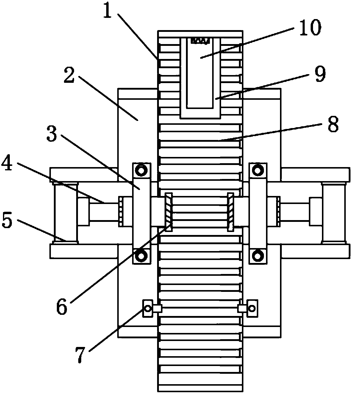
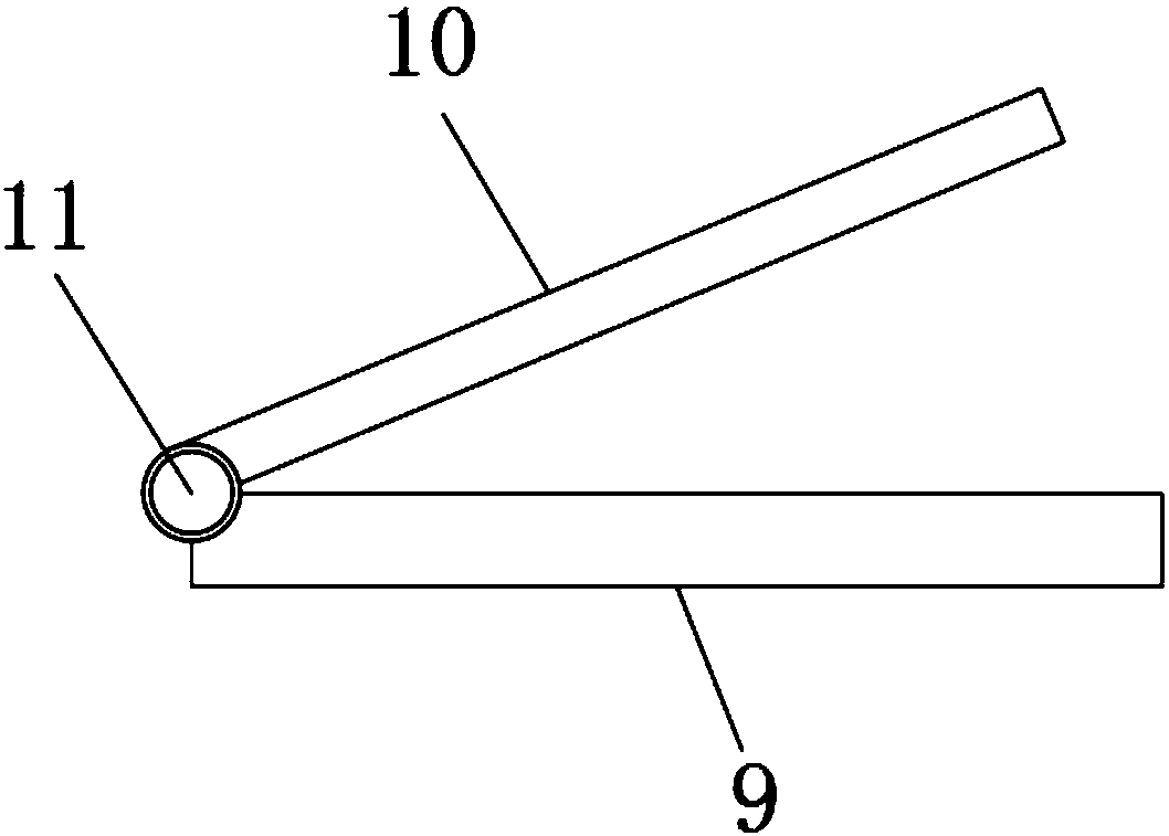
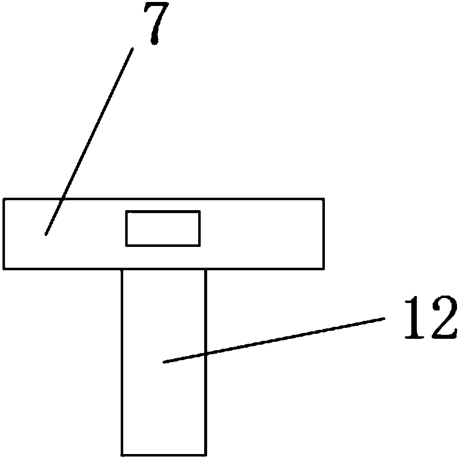
[0020] refer to Figure 1-3 , a clamping mechanism for a tenoning machine, comprising an operating base 2, the top of the operating base 2 is provided with a transfer table 1, the inner side of the transfer table 1 is equidistantly rotated and connected with a roller 8, and the top of the transfer table 1 is a The side is provided with a lower splint 9, and the top of the lower splint 9 is connected with the upper splint 10 through the rotation of the index spring 11. The two sides of the center of the operation base 2 are welded with brackets 5, and the inner side of the bracket 5 is fixed with a telescopic rod 4. The telescopic rod One side of 4 is welded with a cl...


PUM


Abstract

The invention discloses a clamping mechanism for a tenoning machine, which comprises an operating bottom platform, a transmission platform is arranged on the top of the operation bottom platform, and rollers are connected to the inner side of the transmission platform for equidistant rotation, and the top of the transmission platform One side is provided with a lower splint, the top of the lower splint is rotatably connected to an upper splint by an indexing spring, the beam is fixed on the operating platform through a strut, and the other side of the top of the operating platform is rotatably connected to it by a rotating shaft With bayonet. In the present invention, the clamping mechanism for the tenoning machine, firstly, a roller is arranged on the inner side of the transmission platform, and the automatic transportation of the wood can be realized through the rotation of the roller; secondly, the upper splint, the lower splint and the indexing spring The composed splint mechanism can clamp the wood to facilitate the tenoning of the wood, and the clamping support plate and bayonet pin can further fix the wood to prevent the wood from wandering when tenoning.

Description

technical field [0001] The invention relates to the technical field of tenoning machines, in particular to a clamping mechanism for tenoning machines. Background technique [0002] Wooden furniture and office furniture are widely used in people's life and work because of their light structure, low price and various styles. However, in the process of use, it is not difficult to find that most of the furniture used to be processed in place at one time, that is, it was processed into the state of use at one time. In this way, when the manufacturer needs to transport its products, the processed and formed The product is bulky, which greatly increases unnecessary transportation costs; and as a user sometimes needs to move his own wooden furniture and office furniture, it is simply an extraordinary event. In response to this situation, the manufacturer then launched prefabricated furniture, that is, the products produced by the manufacturer are all components, and users only need...

Claims


Application Information

Patent Timeline
Patent Type & Authority Applications(China)
IPC IPC(8): B27F1/00
CPCB27F1/00
Inventor 周进
Owner 高邮市鑫顺机械制造有限公司
Why Eureka
Try Eureka