An electroplating jig for holding slotted needles

A technology of electroplating fixtures and clamping grooves, which is applied in the direction of electrolytic components and electrolysis processes, etc. It can solve the problems that the inner wall of the needle groove cannot be electroplated with a hard chrome layer, the needle groove is worn, and the wear resistance is poor, so as to ensure the quality of electroplating and reasonable structure , to ensure the consistency of the effect

Active Publication Date: 2019-07-23
DONGHUA UNIV +1
View PDF4 Cites 0 Cited by
  • Summary
  • Abstract
  • Description
  • Claims
  • Application Information

AI Technical Summary

Problems solved by technology

[0005] The technical problem to be solved by the present invention is to provide an electroplating fixture for clamping grooved needles, which solves the problem of short service life, low hardness, poor wear resistance, serious wear of needle grooves, and hard plating on the inner wall of needle grooves. chrome problem

Method used


Image

  • An electroplating jig for holding slotted needles
  • An electroplating jig for holding slotted needles
  • An electroplating jig for holding slotted needles

Examples


Embodiment 1

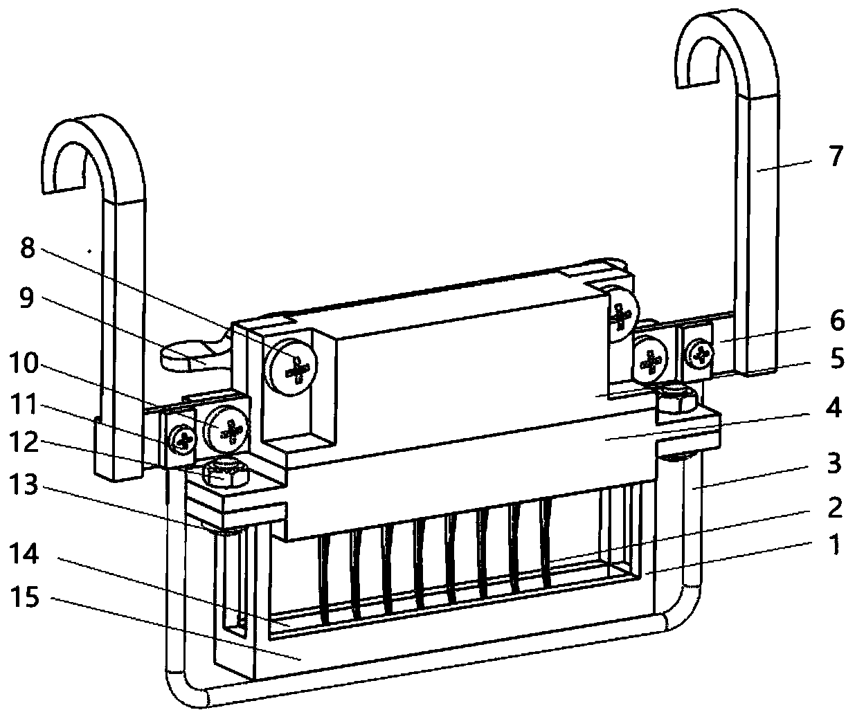
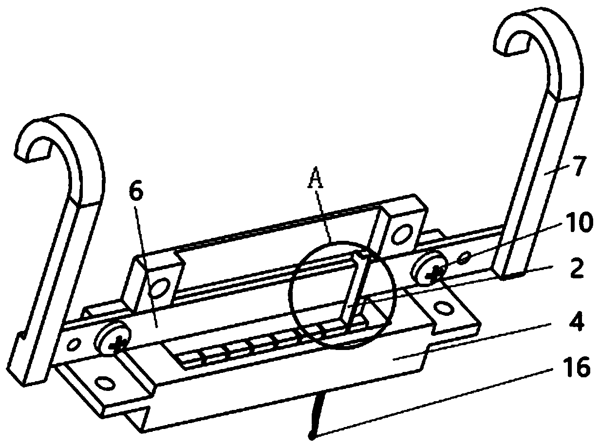
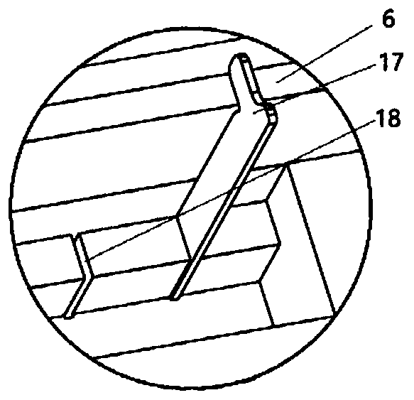
[0023] like Figure 1-5 As shown, an electroplating fixture for clamping a slotted needle includes a hoisting structure, a main body clamping structure and a flow blocking structure, wherein the main body clamping structure includes a plate groove 4, a cover plate 5 and a conductive plate 6, and the The plate groove 4 is connected with the cover plate 5, the conductive plate 6 is sandwiched between the plate groove 4 and the cover plate 5, fixed on the plate groove 4 by the screw a10 and the nut a21, the lower end of the plate groove 4 is provided with a The clamping groove 18 of the clamping groove needle 2, the groove needle 2 includes a groove needle hook 16, a groove needle pin 17 and a groove needle groove 19, and the connection between the cover plate 5 and the conductive plate 6 is provided with a foam glue 20 , for buffering and clamping the slotted needle 2, the choke structure includes a choke frame 1 and a "U"-shaped copper rod 3, the choke frame 1 is composed of a ...


PUM


Abstract

The invention relates to an electroplating clamp for clamping groove pins. The electroplating clamp comprises a hoisting structure, a main body clamping structure and a flow choke structure, wherein the main body clamping structure comprises a plate groove, a cover plate and a conductive plate, the plate groove is connected with the cover plate, the conductive plate is clamped between the plate groove and the cover plate and is fixed on the plate groove through a screw a and a nut a, a clamping groove capable of clamping the groove pins is arranged in the plate groove, a cotton adhesive tape is arranged at the connection of the cover plate and the conductive plate and is used for buffering the clamping effect on the groove pins, the flow choke structure includes a flow choke frame and a U-shaped copper rod, the flow choke frame is composed of a front flow choke plate and a rear flow choke plate, the flow choke frame is connected with the plate groove through a screw b and a nut b, thepin grooves of the groove pins are located in the flow choke frame, and the pin hooks of the groove pins are located between the front flow choke plate and the rear flow choke plate. The electroplating clamp has the advantages of reasonable structure, reliability in clamping, and ensuring of the clamping consistence of the groove pins.

Description

technical field [0001] The invention belongs to the technical field of electroplating treatment for grooved needles of warp knitting machines, in particular to an electroplating fixture for clamping grooved needles. Background technique [0002] Knitting equipment is the key equipment for the knitting machine to directly contact with the fiber and shape the fabric during the weaving process, and it plays a vital role in the quality of the fabric. During the knitting process, poor surface roughness and poor wear resistance of knitting equipment are likely to cause the knitting equipment to pull and break the fabric. Therefore, the influence of surface defects on fabric quality during knitting needle operation can be compensated by appropriate surface treatment of knitting equipment, and the service life of knitting equipment and fabric quality can be improved. [0003] The warp knitting machine groove needle is used in conjunction with the needle core. The needle core recipr...

Claims


Application Information

Patent Timeline
Patent Type & Authority Patents(China)
IPC IPC(8): C25D17/08
CPCC25D17/08
Inventor 朱世根黄园白云峰朱巧莲苏庆德
Owner DONGHUA UNIV
Why Eureka
Try Eureka