Automatic loading machine of strain gauge of terminals

A strain gauge and loader technology, which is applied in mechanical equipment, electromagnetic measuring devices, electric/magnetic solid deformation measurement, etc. Guaranteed precision, uniform glue effect

Active Publication Date: 2018-03-02
安徽明亮面业股份有限公司
View PDF7 Cites 11 Cited by
  • Summary
  • Abstract
  • Description
  • Claims
  • Application Information

AI Technical Summary

Problems solved by technology

[0003] There may be the following problems when attaching strain gauges to the existing terminals. First, the lowering position of the strain gauges is not accurate, resulting in a deviation in the pasting position, or when pressing the material, the pressure is directly applied to the narrow ring structure, which may easily cause the pasted strain gauges to be damaged. Slippage occurs and the correct pasting position is shifted, which affects the measurement sensitivity and accuracy; secondly, when pressing down, if the pressing force is too small, the strain gauge will not be firmly pasted, so that it will not It is easy to cause glue failure and affect the service life of the terminal. If the pressing force is too large, the strain gauge may be damaged

Method used


Image

  • Automatic loading machine of strain gauge of terminals
  • Automatic loading machine of strain gauge of terminals
  • Automatic loading machine of strain gauge of terminals

Examples


Embodiment Construction

[0038] In order to enable those skilled in the art to better understand the technical solution of the present invention, the present invention will be described in detail below in conjunction with the accompanying drawings. The description in this part is only exemplary and explanatory, and should not have any limiting effect on the protection scope of the present invention. .

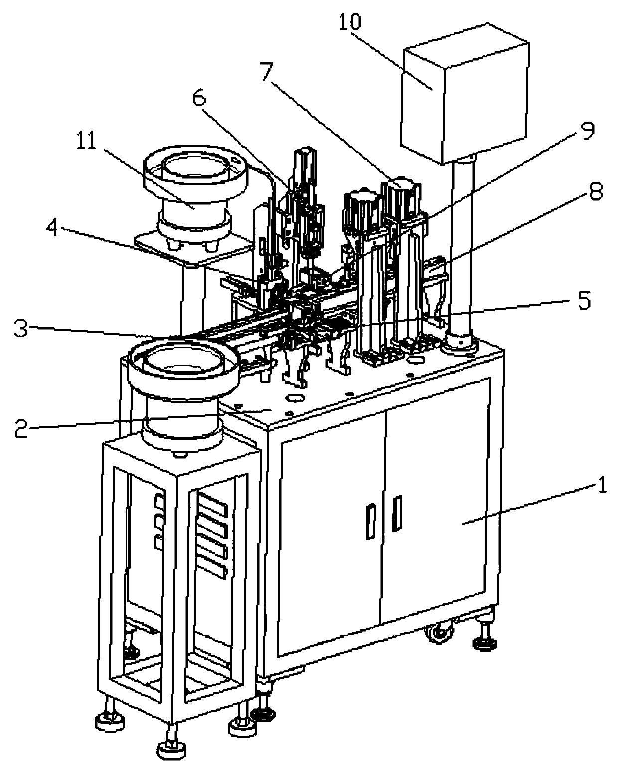
[0039] Such as Figure 1-Figure 13 As shown, the structure of the present invention is: a terminal strain gauge automatic loading machine, which includes a main frame 1 and a power distribution control box arranged in the main frame 1, and the upper end of the main frame 1 is fixedly installed with The frame bottom plate 2, the middle part of the upper end of the frame bottom plate 2 is provided with a terminal conveying slideway device 8, and a strain gauge conveying device 5 is arranged above the terminal conveying slideway device 8, and above the strain gauge conveying device 5 From left to right, ...


PUM


Abstract

The present invention relates to an automatic loading machine of strain gauges of terminals. The automatic loading machine comprises a main body rack and a rack base plate. An upper end of the rack base plate is provided with a terminal feeding device. The tail end of the terminal feeding device is butted with a terminal conveying slideway device. One side of the terminal conveying slideway deviceis successively provided with a dispensing device, a strain gauge blanking device and a terminal fixing device from left to right, and the other side of the terminal conveying slideway device is successively provided with a strain gauge conveying device, a pressing device and a human-computer interface. The dispensing device is connected to a strain gauge feeding device. The strain gauge conveying device is positioned between the dispensing device and the strain gauge blanking device. The terminals are conveyed by the terminal conveying slideway device, the strain gauges are clamped by a material receiving head of a front and back clamping mechanism and moved below a dispensing head to achieve dispensing, the strain gauges are conveyed below the strain gauge blanking device by a left andright moving mechanism, a blanking head of the strain gauge blanking device descends and passes through inner rings of the strain gauges, the material receiving head is withdrawn, the strain gauges are lowered on the terminals along the blanking head, the whole structure is compact, and the degree of automation is high.

Description

technical field [0001] The invention relates to the field of mechanical equipment, in particular to a fully automatic loader for strain gauges of terminals. Background technique [0002] Strain gauges, also known as strain gauges, are components used to measure strain composed of sensitive grids, which can convert changes in strain on mechanical components into changes in resistance. As sensing elements, strain gauges need to be firmly pasted on the components. At the measuring point, the pressurization method after the strain gauge is pasted on the test piece (such as an elastic ring) is determined by the sticking position and the convenience of operation. The strength of the clamp can only be determined by the clip itself. For the test piece that cannot be clamped or clamped unstable by the clamp due to the deep sticking position or too small area of ​​the sticking part, it is generally necessary to design a special pressure device. [0003] There may be the following pro...

Claims


Application Information

Patent Timeline
Patent Type & Authority Applications(China)
IPC IPC(8): F16B11/00G01B7/16
CPCF16B11/006G01B7/18
Inventor 邓君杨坤
Owner 安徽明亮面业股份有限公司
Why Eureka
Try Eureka