Low voltage reactive compensation cabinet

A compensation cabinet and low-voltage technology, applied in the field of electrical cabinets, can solve the problems of inconvenient disassembly, inconvenience, and placement of the main electrical components on the top of the power distribution cabinet.

Inactive Publication Date: 2018-03-02
WUHU ZHUOYA ELECTRIC
View PDF6 Cites 6 Cited by
  • Summary
  • Abstract
  • Description
  • Claims
  • Application Information

AI Technical Summary

Problems solved by technology

[0002] Low-voltage reactive power compensation cabinets are very commonly used at present. Due to the differences in climate in various places, the placement of electrical components inside the low-voltage reactive power compensation cabinets is also different. For relatively humid areas, the main components inside the low-voltage reactive power compensation cabinets Electrical components are usually placed on the top of the distribution cabinet to prevent the moisture on the ground from causing damage to the main electrical components and causing serious economic losses
[0003] Regarding the placement of the above-mentioned main electrical components, generally speaking, maintenance personnel often need to use other tools to assist them, such as stools or ladders, etc., when maintaining them, which causes great inconvenience. The process will also be very tricky. Another situation is that it will be very inconvenient to install and disassemble the heavy main electrical components. In addition, in some areas with soft ground and long-term resonance of passing vehicles action can also cause damage to electrical components
[0004] CN105870796A discloses a heat-dissipating electrical cabinet with an adjustable internal space. Although the electrical cabinet can change the air flow in the cabinet through heat dissipation to a certain extent, and can improve the degree of damage to the main electrical components caused by high air humidity, but its The effect of the change is not as good as placing the main electrical components on the top of the power distribution cabinet. In addition, it cannot solve the problem of damage to electrical components due to resonance. It is also a problem that the rain cannot be protected during emergency repairs in rainy days.

Method used


Image

  • Low voltage reactive compensation cabinet

Examples


Embodiment Construction

[0036] Specific embodiments of the present invention will be described in detail below in conjunction with the accompanying drawings. It should be understood that the specific embodiments described here are only used to illustrate and explain the present invention, and are not intended to limit the present invention.

[0037] In the present invention, unless otherwise specified, the orientation words included in the term such as "up, down, left, right, front, back, inside and outside" only represent the orientation of the term in the normal use state, or the common name understood by those skilled in the art. , and should not be construed as a limitation of this term.

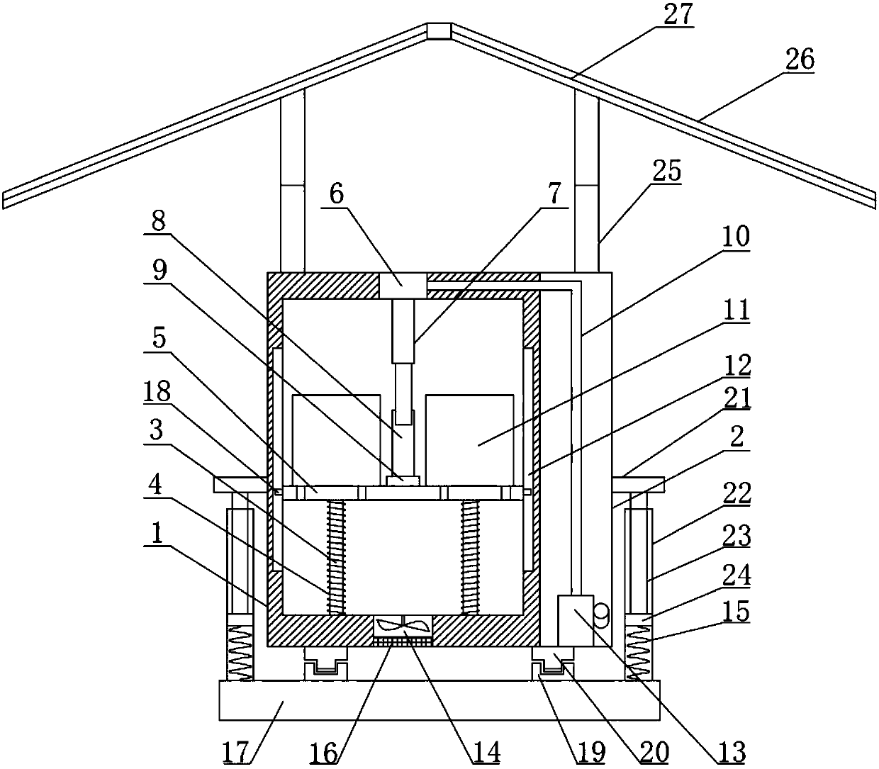
[0038] see figure 1 The low-voltage reactive power compensation cabinet shown, the low-voltage reactive power compensation cabinet includes a cabinet body and a base 17, the upper end surface of the base 17 is provided with a plurality of support tubes 22 along its circumferential direction, and the support tu...


PUM


Abstract

The invention discloses a low voltage reactive compensation cabinet. The upper end surface of a base is provided with multiple supporting pipes along the circumferential direction. The supporting pipes are internally provided with elastic members. The side wall of the cabinet body is provided with multiple plug pins which are matched with the supporting pipes. Multiple plug pins are detachably plugged in the corresponding supporting pipes and contacted with the elastic members so that the cabinet body is enabled to be elastically and detachably fixed on the base. One end of supporting columnsis fixedly connected on the external top end of the cabinet body, and the other end is fixedly connected with a rainshed. The cabinet body is internally provided with an electrical room and an operation room which are arranged in a spaced way from the left to the right. The electrical room is internally provided with a bearing mechanism which can elevate along a vertical direction. The operation room is internally provided with a control mechanism which is connected with the bearing mechanism and can control elevating of the bearing mechanism. According to the low voltage reactive compensationcabinet, auxiliary appliances are not required and the process of installation, disassembling and maintenance of heavy main electrical components is facilitated, rain sheltering can be realized and the great damping effect can also be realized.

Description

technical field [0001] The invention relates to the field of electrical cabinets, in particular to a low-voltage reactive power compensation cabinet. Background technique [0002] Low-voltage reactive power compensation cabinets are very commonly used at present. Due to the differences in climate in various places, the placement of electrical components inside the low-voltage reactive power compensation cabinets is also different. For relatively humid areas, the main components inside the low-voltage reactive power compensation cabinets Electrical components are usually placed on the top of the distribution cabinet to prevent the moisture on the ground from causing damage to the main electrical components and causing serious economic losses. [0003] Regarding the placement of the above-mentioned main electrical components, generally speaking, maintenance personnel often need to use other tools to assist them, such as stools or ladders, etc., when maintaining them, which cau...

Claims


Application Information

Patent Timeline
Patent Type & Authority Applications(China)
IPC IPC(8): H02B1/30H02B1/28H02B1/54
CPCH02B1/303H02B1/28H02B1/54
Inventor 阮辰廷徐伟查晓健
Owner WUHU ZHUOYA ELECTRIC
Why Eureka
Try Eureka