

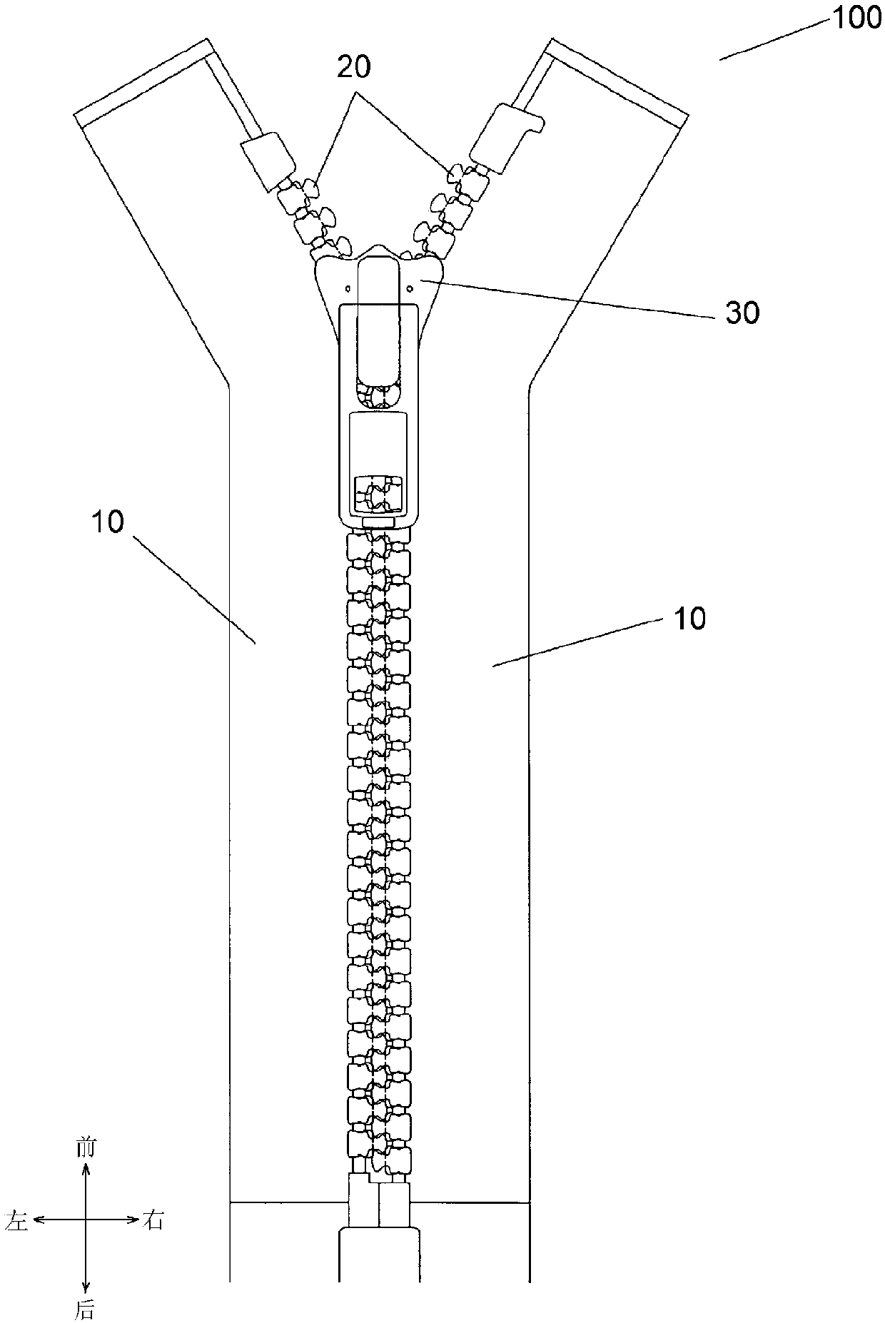
Chain tooth, chain strap and zipper
A technology of chain teeth and chain belts, applied in the field of chain belts and zippers, to reduce weight, meet strength requirements, and save costs
- Summary
- Abstract
- Description
- Claims
- Application Information
AI Technical Summary
Problems solved by technology
Method used
Image

Examples
Embodiment approach 1
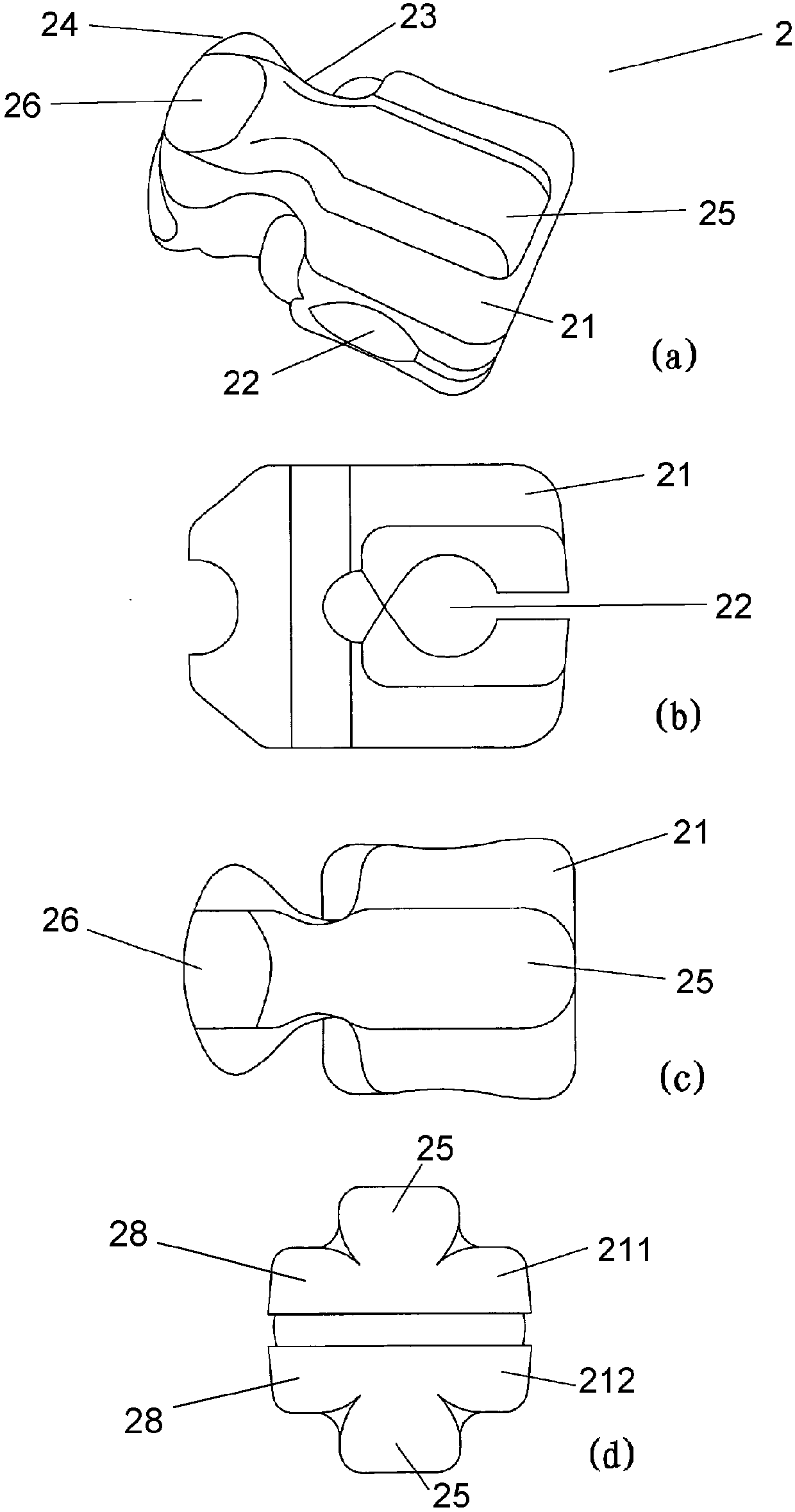
[0046] image 3 are four views of the fastener element in the first embodiment of the present invention, where image 3 (a) is a stereogram, image 3 (b) is the main view, image 3 (c) is a top view, image 3 (d) is a right view. The fastener element 2 of the first embodiment includes a body portion 21 , a mounting portion 22 , a neck portion 23 and a head portion 24 . The body part 21 includes an upper body part 211 and a lower body part 212 . The mounting part 22 is used for setting the tape of the zipper, and the neck part 23 connects the main body part 21 and the head part 24 .
[0047] At least one of the upper body portion 211 and the lower body portion 212 of the fastener element 2 includes a convex portion 25 and a base portion 28, the convex portion 25 extends from the base portion 28, and the convex portion 25 is located in the middle of the chain element 2 in the front-rear direction And extend along the left-right direction of chain tooth 2. for figure 2 T...
Embodiment approach 2
[0053] Figure 4 are five views of the fastener element in the second embodiment of the present invention, where Figure 4 (a) is a stereogram, Figure 4 (b) is the main view, Figure 4 (c) is a top view, Figure 4 (d) is the right view, Figure 4 (e) is a left view. The following will focus on the points different from the first embodiment, and the description of the same parts as the first embodiment will be omitted.
[0054] The element 2 in the second embodiment also has the convex part 25 and the inclined part 26 similarly to the first embodiment. In the fastener element 2 in the second embodiment, the protrusion 27 is added to the first embodiment. Preferably, the protrusions 27 are symmetrically formed on both sides of the protrusion 25 in the front-rear direction of the fastener element 2 . Further preferably, the centerline of the protruding portion 27 is consistent with the centerline of the mounting portion 22 of the fastener element 2 in the vertical directi...
PUM
 Abstract
Description
Claims
Application Information