Electron beam selective preheating scanning method

A scanning method and electron beam technology, applied in the field of metal additive manufacturing, can solve the problems of reduced recycling rate of powder materials, uneven temperature distribution of formed parts, and increased electron beam scanning area, so as to reduce temperature inhomogeneity, Increased reuse rate, the effect of increased reuse rate

Inactive Publication Date: 2018-03-06
XIAN ZHIRONG METAL PRINTING SYST CO LTD
View PDF8 Cites 17 Cited by
  • Summary
  • Abstract
  • Description
  • Claims
  • Application Information

AI Technical Summary

Problems solved by technology

[0006] Although the above two electron beam preheating scanning methods can reduce the uneven temperature distribution of the formed part, thereby reducing the warpage of the formed part during the forming process, there are still two main shortcomings: (1) Both methods are The overall preheating scanning of the powder bed increases the scanning area of ​​the electron beam and reduces its efficiency; (2) In addition to the powder materials that need to be melted for forming, other powder materials that are used as supporting parts are also subject to high temperature thermal effects Sintering occurs, which is not only difficult to clean up after forming, but also reduces the recycling rate of this part of the powder material, or even makes it impossible to reuse

Method used


Image

  • Electron beam selective preheating scanning method
  • Electron beam selective preheating scanning method
  • Electron beam selective preheating scanning method

Examples


Embodiment Construction

[0021] In order to facilitate the understanding of the present invention, the present invention will be described more fully below with reference to the associated drawings. Preferred embodiments of the invention are shown in the accompanying drawings. The above are only preferred embodiments of the present invention, and are not intended to limit the patent scope of the present invention. Any equivalent structure or equivalent process conversion made by using the description of the present invention and the contents of the accompanying drawings, or directly or indirectly used in other related technical fields , are all included in the scope of patent protection of the present invention in the same way.

[0022] Unless otherwise defined, all technical and scientific terms used herein have the same meaning as commonly understood by one of ordinary skill in the technical field of the invention. The terminology used herein in the description of the present invention is only for ...


PUM


Abstract

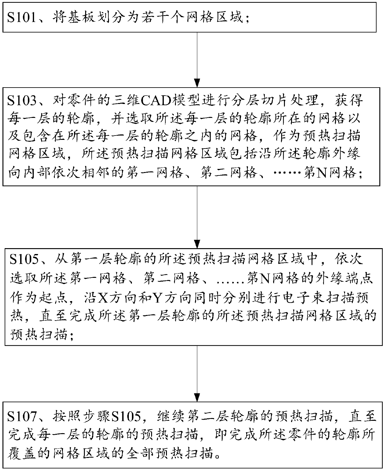
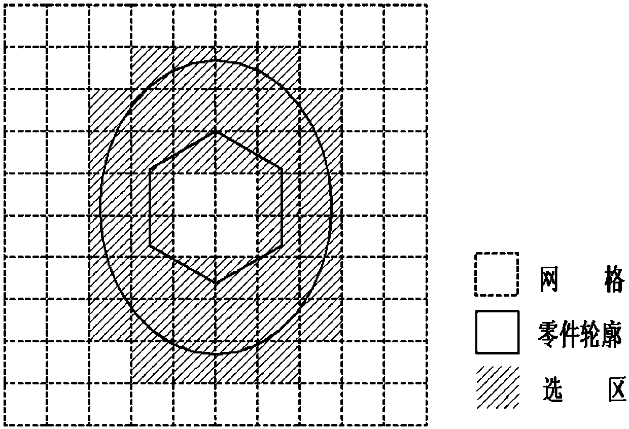
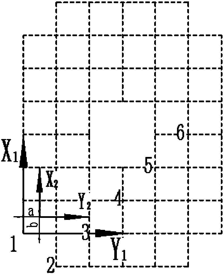
The invention provides an electron beam selective preheating scanning method. The electron beam selective preheating scanning method comprises the steps that S101, a base plate is divided into a plurality of grid areas; S103, a three-dimensional CAD model of a part is subjected to layered slicing so as to obtain a contour of each layer, and grids where the contours of all the layers are located and grids contained in the contours of all the layers are selected to serve as preheating scanning grid areas which each comprise the first grid, the second grid...the N grid which are sequentiallyadjacent from the outer edges of the contours to the interiors; S105, the outer edge end points of the first grid, the second grid...the N grid in the preheating scanning grid area of the contourof the first layer are sequentially selected to serve as starting points, and electron beam preheating scanning is conducted in the X and Y directions simultaneously; and S107, according to the step 105, preheating scanning of the contour of the second layer is continued till preheating scanning of the contour of each layer is completed. According to the electron beam selective preheating scanningmethod, a powder bed can be preheated, temperature unevenness is reduced, warping deformation is reduced, and the material utilization rate can also be increased.

Description

technical field [0001] The invention relates to the technical field of metal additive manufacturing, in particular to an electron beam selective area preheating scanning method. Background technique [0002] Additive Manufacturing (AM) technology, also known as 3D printing technology, is based on the principle of discrete-stacking, and manufactures entities by layer-by-layer methods of materials, mainly including fused deposition modeling (FDM), selective laser Sintering technology (SLS), stereolithography (SLA), selective melting technology (SLM) and electron beam melting technology (EBM), etc. [0003] Electron beam melting (Electron Beam Melting, EBM) technology is a kind of high-performance metal additive manufacturing technology, which is similar to laser selective melting technology. Firstly, slice the 3D CAD model of the part through professional data processing software, obtain the part outline information of each layer, and plan the scanning path; then use the high...

Claims


Application Information

Patent Timeline
Patent Type & Authority Applications(China)
IPC IPC(8): B22F3/105B33Y10/00
Inventor 郭光耀贺智锋
Owner XIAN ZHIRONG METAL PRINTING SYST CO LTD
Why Eureka
Try Eureka