Industrial by-product gypsum calcining furnace

A technology of industrial by-product gypsum and calciner, which is applied in the field of phosphogypsum calciner and industrial by-product gypsum production equipment, which can solve the problems of pollution and waste of gypsum raw materials, and achieve the effects of reducing costs, saving energy and avoiding waste

Active Publication Date: 2017-06-30
ZHENGZHOU SUNDY BUILDING TECH
View PDF10 Cites 9 Cited by
  • Summary
  • Abstract
  • Description
  • Claims
  • Application Information

AI Technical Summary

Problems solved by technology

However, in the existing drying and calcining furnace, when the air is drawn by the fan, the powdery phosphogypsum particles are taken away together, which causes waste of gypsum raw materials, and the air taken away is discharged into the atmosphere, and the gypsum particles contained therein will also be discharged into the atmosphere. air pollution

Method used


Image

  • Industrial by-product gypsum calcining furnace
  • Industrial by-product gypsum calcining furnace
  • Industrial by-product gypsum calcining furnace

Examples


Embodiment 1

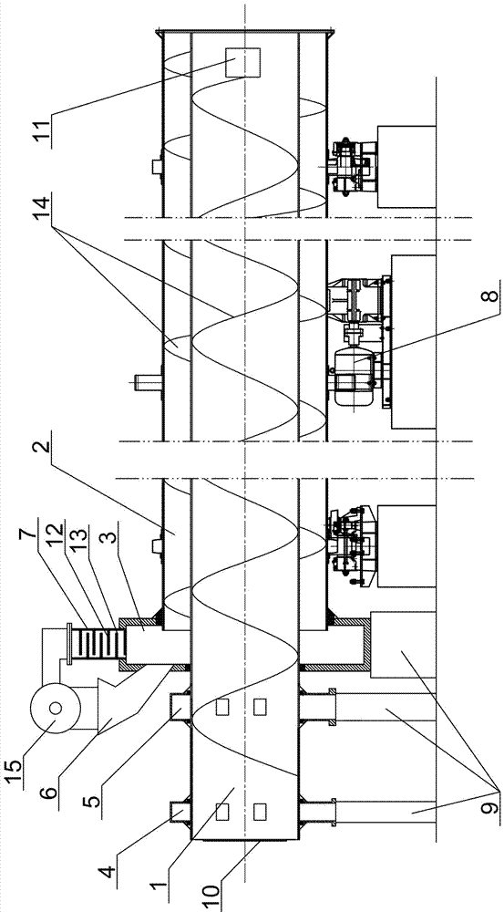
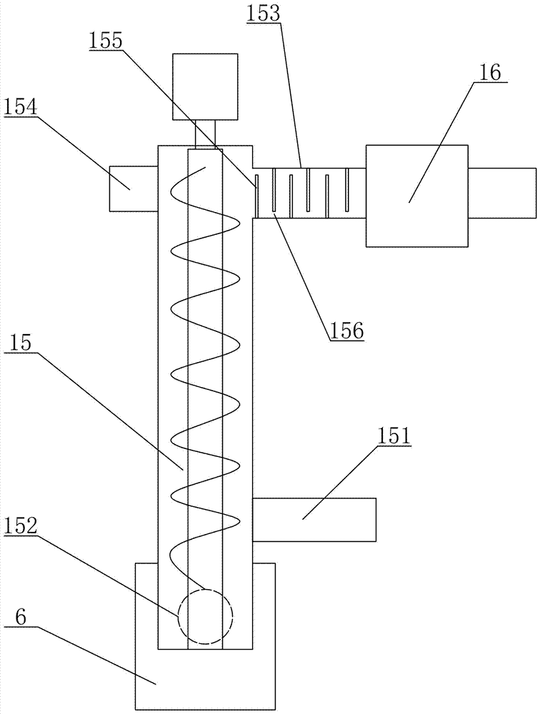
[0026] Such as figure 1 , figure 2 , image 3 As shown, an industrial by-product gypsum calciner includes an inner cylinder 1, an outer cylinder 2, a kiln head 3, anhydrous gypsum outlet 4, hemihydrate gypsum outlet 5, a feed hopper 6, an air outlet 7, The power transmission device 8 and the supporting device 9, the inner cylinder 1 is inserted in the outer cylinder 2, the length of the inner cylinder 1 is longer than the length of the outer cylinder 2, and the end of the inner cylinder 1 located outside the outer cylinder 2 is provided with a hot air inlet 10, and the hot air inlet 10 corresponds to the flame-throwing furnace, one end of the inner cylinder 1 located in the outer cylinder 2 is fixedly connected to the tail end of the outer cylinder 2, the front end of the outer cylinder 2 is provided with a kiln head 3, and the tail end of the outer cylinder 2 is closed , the head end of the outer cylinder 2 communicates with the inner cavity of the kiln head 3, and the kil...

Embodiment 2

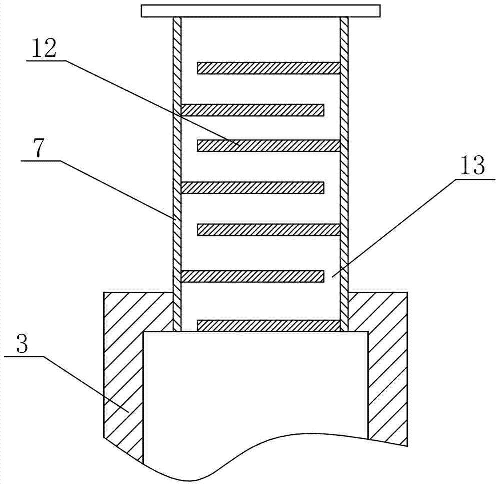
[0030] Such as Figure 4 As shown, repeating Example 1, there are the following differences: the baffle plate 12 is arranged obliquely downward in the air outlet 7, and the material contained in the airflow drawn by the air outlet 7 falls back on the baffle plate 12 after being blocked by the air outlet. On the surface of the plate 12 , the baffle 12 arranged obliquely downward is beneficial for the material to slide down along the baffle 12 back into the outer cylinder 2 .

[0031] The ventilation hole 13 of the present invention is a through hole arranged on the baffle plate 12, and the through holes on two adjacent baffle plates 12 are staggered from each other, and the baffle plate 12 closes the cross-section of the entire air outlet 7, and the through hole is set on the baffle plate 12. hole. The gaps between the mutually staggered through holes and the baffles 12 can also form a labyrinth ventilation channel. In order to ensure the blocking effect of the baffles 12, wh...


PUM


Abstract

The invention relates to an industrial by-product gypsum calcining furnace. The furnace includes an inner cylinder, an outer cylinder, a grate cooler, an anhydrous gypsum discharge hole, a hemihydrate gypsum discharge hole, a feeding hole, a suction opening, a power drive device and a support device; a plurality of baffles are arranged in the suction opening, an air hole is reserved between each baffle and the inner wall of the suction opening, the air holes are alternately formed in the two sides of the inner wall of the suction opening, and gaps between the air holes and the baffles form a labyrinth-like air draft channel. According to the industrial by-product gypsum calcining furnace, the baffles arranged like a labyrinth are installed in the suction opening of the grate cooler of an existing gypsum drying calcining furnace, the baffles arranged like a labyrinth ceaselessly change the flow direction of air flow in the flowing process of the air flow, powdered gypsum particles contained in the air flow are settled and drop in the drying calcining furnace, waste of gypsum raw materials is thus avoided, and the purpose of reducing cost, saving energy and reducing pollutant emission is achieved.

Description

technical field [0001] The invention relates to the technical field of industrial by-product gypsum production equipment, in particular to a calciner for industrial by-product gypsum, especially phosphogypsum. Background technique [0002] Gypsum is a chemical composition of calcium sulfate containing crystal water. In daily life, gypsum is divided into natural gypsum and chemical gypsum. Natural gypsum is a mineral containing two crystal water. Chemical gypsum is used when producing fertilizers and other chemical raw materials. The waste produced, with the improvement of the emission requirements of coal-fired boilers, the by-product of the desulfurization process is called desulfurization gypsum; the waste gypsum produced by the production of fertilizers and other phosphides is called phosphogypsum because it contains phosphorus oxide. The application of building materials is mostly to calcinate raw gypsum containing two crystal waters into gypsum containing half crystal w...

Claims


Application Information

Patent Timeline
Patent Type & Authority Applications(China)
IPC IPC(8): C04B11/036
CPCC04B11/036
Inventor 赵嘉珩赵建纲
Owner ZHENGZHOU SUNDY BUILDING TECH
Why Eureka
Try Eureka