
Transmission shaft end face forked end tooth key pulling tool

A drive shaft and end face technology, applied in the field of mechanical parts processing, can solve problems such as restricting enterprise development, rising processing costs, complex positioning structures, etc., and achieving the effects of reducing labor intensity, low cost, and reliable connection

Inactive Publication Date: 2018-03-06
杨锋
View PDF0 Cites 0 Cited by
  • Summary
  • Abstract
  • Description
  • Claims
  • Application Information

AI Technical Summary

Problems solved by technology

[0002] At present, with the development of social economy, it is found in production practice that due to the increase in labor costs, the pull key for the end face of the drive shaft needs to be operated by workers with rich experience, and its positioning structure is complex, requiring repeated detection and positioning. As a result, the processing cost increases and the production efficiency is low, which seriously restricts the development of the enterprise. In order to improve and break through this problem, according to the positioning characteristics and processing requirements, it is necessary to design and improve a transmission shaft end face fork end tooth with a high degree of generalization and easy operation. Pull key tooling

Method used


Image

  • Transmission shaft end face forked end tooth key pulling tool

Examples


Embodiment 1

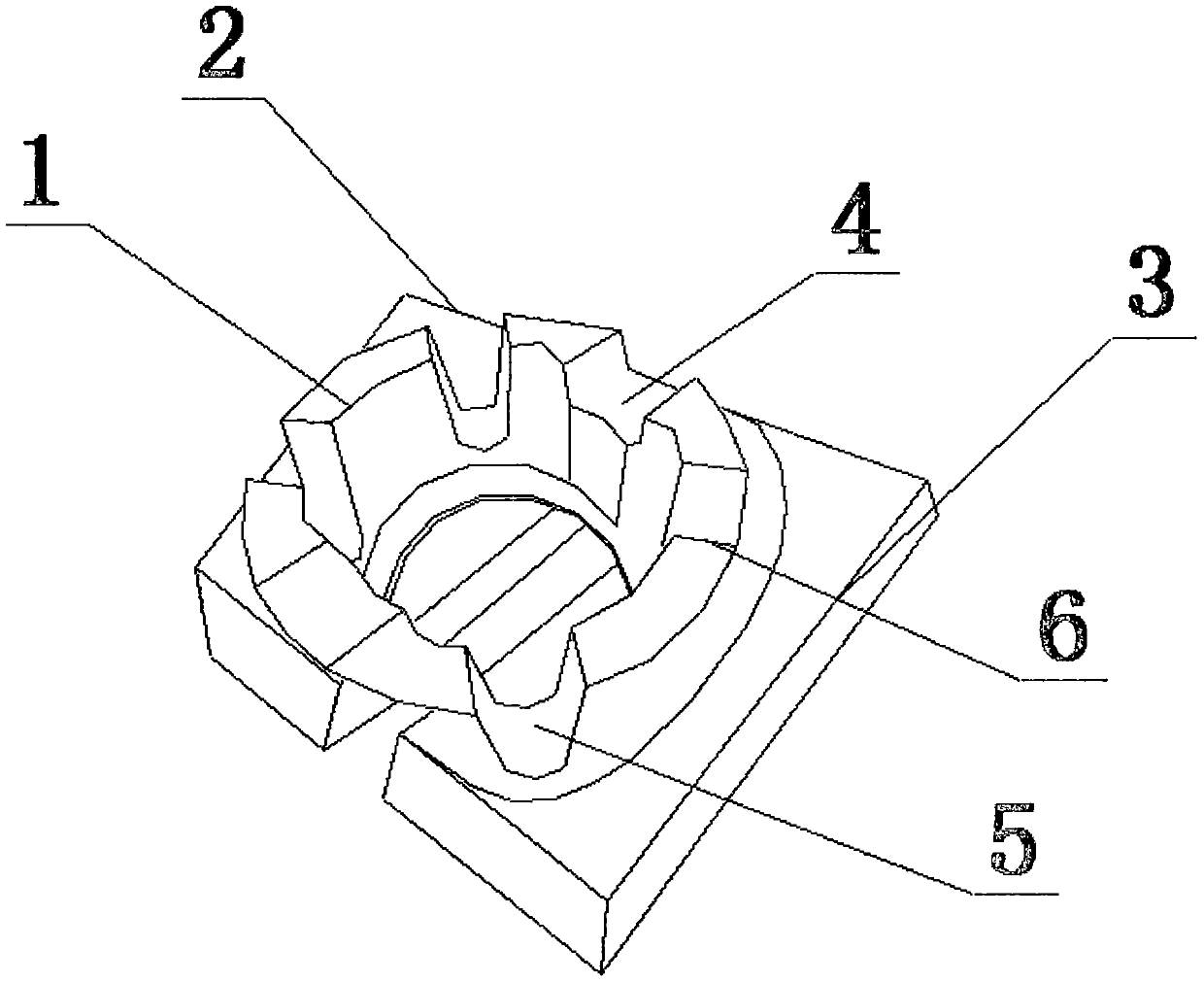
[0018] Such as figure 1 As shown, a tooling tool for pulling keys with fork-end teeth on the end face of a drive shaft includes a left base 2, a right base 3, and a positioning table 1. The positioning table 1 is cylindrical, and the positioning table 1 The left base 2 and the right base 3 are connected below. The upper edge of the positioning table 1 is symmetrically provided with two U-shaped grooves A4, two U-shaped grooves B5, and two U-shaped grooves C6. The width of the U-shaped groove A4 is greater than that of the U-shaped groove B5 and U-shaped groove C6, and the depth of the U-shaped groove A4 is smaller than that of the U-shaped groove B5 and U-shaped groove C6; the U-shaped groove B5 and U-shaped groove C6 have the same specifications , The left base 2 and the right base 3 are symmetrically arranged below the positioning table 1.

[0019] A hydraulic clamping table is arranged above the positioning table 1.

[0020] The present invention adopts a positioning table, a ...

Embodiment 2

[0023] Such as figure 1 As shown, a tooling tool for pulling keys with fork-end teeth on the end face of a drive shaft includes a left base 2, a right base 3, and a positioning table 1. The positioning table 1 is cylindrical, and the positioning table 1 The left base 2 and the right base 3 are connected below. The upper edge of the positioning table 1 is symmetrically provided with two U-shaped grooves A4, two U-shaped grooves B5, and two U-shaped grooves C6. The width of the U-shaped groove A4 is greater than that of the U-shaped groove B5 and U-shaped groove C6, and the depth of the U-shaped groove A4 is smaller than that of the U-shaped groove B5 and U-shaped groove C6; the U-shaped groove B5 and U-shaped groove C6 have the same specifications , The left base 2 and the right base 3 are symmetrically arranged below the positioning table 1.

[0024] The positioning table 1 and the left base 2, the positioning table 1 and the right base 3 are all welded.

[0025] Both the left ba...


PUM

PropertyMeasurementUnit
Thicknessaaaaaaaaaa
Wall thicknessaaaaaaaaaa

Abstract

The invention relates to a fork-end gear pull key tooling on the end face of a transmission shaft, which includes a left base, a right base and a positioning platform, the positioning platform is cylindrical, and the left base is connected to the bottom of the positioning platform and the right base, the upper edge of the positioning table is symmetrically provided with 2 U-shaped grooves A, 2 U-shaped grooves B, and 2 U-shaped grooves C, and the width of the U-shaped groove A is greater than that of the U-shaped groove B and U-shaped groove C, the depth of the U-shaped groove A is smaller than that of U-shaped groove B and U-shaped groove C; the specifications of the U-shaped groove B and U-shaped groove C are the same, and the left base and the right The base is arranged symmetrically under the positioning platform; the invention has the advantages of high generalization, convenient operation, simple structure, low positioning difficulty, convenient use, high precision and low cost.

Description

Technical field [0001] The invention belongs to the technical field of machining parts and components, and in particular relates to a tool for pulling a key on the end face of a transmission shaft. Background technique [0002] At present, with the development of society and economy, it has been found in production practice that due to the increase in labor costs, the pull key for the fork end teeth of the drive shaft needs to be operated by workers with rich experience, and its positioning structure is complex, requiring repeated detection and positioning. The increase in processing costs and low production efficiency have severely restricted the development of the enterprise. In order to improve and break through this problem, according to the positioning characteristics and processing requirements, it is necessary to design and improve a high degree of generalization and easy operation of the drive shaft end face prong tooth Pull key tooling. Summary of the invention [0003] ...

Claims


Application Information

Patent Timeline
IPC IPC(8): B23D41/06
CPCB23D41/06
Inventor 杨锋
Owner 杨锋
Learn More