Printed product inspection machine

A detection mechanism and machine tool technology, applied in the direction of winding strips, sending objects, processing thin materials, etc., can solve the problems of cumbersome, reduce the working efficiency of the inspection machine, etc., and achieve the effect of saving space

Pending Publication Date: 2018-03-06
江苏飞视文化发展有限公司
View PDF10 Cites 5 Cited by
  • Summary
  • Abstract
  • Description
  • Claims
  • Application Information

AI Technical Summary

Problems solved by technology

During the use of this printing machine, in order to fix the end of the packaging bag on the paper tube, it is necessary to manually wind the packaging bag on the winding roller for several turns and manually turn the winding roller to embed the end of the packaging bag on the paper tube. Between the packaging bag and the paper tube to fix the packaging bag on the winding roller, and while manually rotating the winding roller, it is necessary to pull the packaging bag to the side of the winding roller to obtain enough length to wrap on the paper cylinder, so that Subsequent packaging bags can be wound on the paper tube of the winding roller driven by the winding roller, but this manual operation is too cumbersome and reduces the working efficiency of the inspection machine

Method used


Image

  • Printed product inspection machine
  • Printed product inspection machine
  • Printed product inspection machine

Examples


Embodiment 1

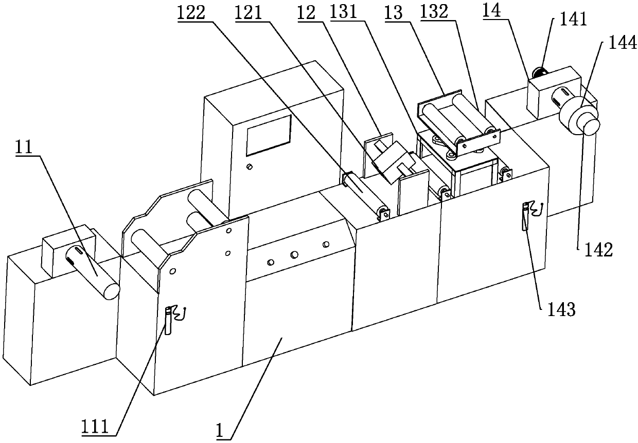
[0029] Embodiment 1, a product inspection machine, such as figure 1 As shown, a machine tool 1 is included, and a feed roller 11 , a detection mechanism 12 , a tension mechanism 13 and a winding mechanism 14 are sequentially arranged on the machine tool 1 .

[0030] The feeding roller 11 is an air-expanding shaft, which is used to place the roll of the packaging bag to be detected. The side of the machine tool 1 near the feeding roller 11 is provided with an air gun-111. After the packaging bag roll is set on the feed roller 11, the feed roller 11 is inflated by the air gun one 111, so that the key bar inside it protrudes and touches the inner ring of the packaging bag roll roller to fix it.

[0031] The detection mechanism 12 includes a strobe light 121, on both sides of the strobe light 121, several driven rollers 122 that play a role in tension are arranged, and the end of the packaging bag on the feeding roller 11 is pulled out and pulled out from the strobe light. The dr...

Embodiment 2

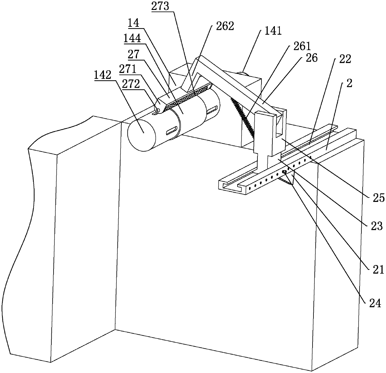
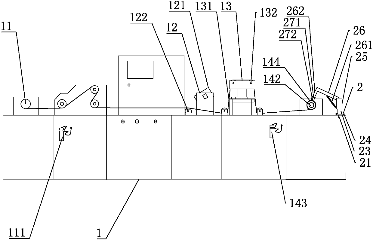
[0034] Embodiment 2, a packaging bag inspection machine, differs from Embodiment 1 in that, as figure 2 and 3 As shown, on the machine tool 1, a support plate 2 is arranged on the side of the motor 141 facing the winding roller 142, a reinforcing rib 21 is arranged under the support plate 2, a slide rail 22 is arranged on the support plate 2, and a slide rail 22 is slidably connected with a slide rail. Block 23, the slide rail 22 is provided with a positioning bolt 24 for fixing the slide block 23, the slide block 23 is vertically provided with a support rod 25, the support rod 25 upper end is hinged with a cantilever 26 towards the winding roller 142, the cantilever 26 and the support The side of the rod 25 facing the winding roller 142 is fixedly connected with a tension spring 261, so that under the action of the tension spring 261, the cantilever 26 has a tendency to rotate towards the winding roller 142; A crossbeam 27 parallel to the winding roller 142 is arranged unde...

Embodiment 3

[0038] Embodiment 3, a packaging bag inspection machine, differs from Embodiment 2 in that, as Figure 4 As shown, the bending part 262 is connected to the crossbeam 27 through the universal joint 28, the end of the crossbeam 27 is provided with an arc-shaped plate 29 along the conveying direction, and a pair of pressure rollers parallel to the crossbeam 27 are arranged between the arc-shaped plates 29 291.

[0039] The specific implementation instructions are as follows:

[0040] Two pinch rollers 291 increase the pinch span of the packaging bag. With the continuous winding of the winding roller 142, the packaging bag on the paper tube 144 is constantly thickened, and the cantilever 26 is continuously lifted, so that the center of the arc plate 29 gradually deviates from the center of the winding roller 142, and the universal The hinge joint 28 can adjust the angle of the arc-shaped plate 29, so that the arc-shaped plate 29 remains concentric with the take-up roller 142 all t...


PUM


Abstract

The invention discloses a packaging bag inspection machine, belongs to the field of inspection machines, and aims to provide a printed product inspection machine. According to the printed product inspection machine, products can be rapidly fixed to paper tubes of a wind-up roller, so that the working efficiency is improved. The technical scheme of the packaging bag inspection machine is characterized by comprising a machine tool, a feeding roller, a detection mechanism, a tensioning mechanism and a wind-up mechanism, wherein the feeding roller, the detection mechanism, the tensioning mechanismand the wind-up mechanism are sequentially arranged on the machine tool; the wind-up mechanism comprises the wind-up roller which is driven by a motor and is used for being sleeved with the paper tubes; a supporting plate is arranged on the machine tool, and a supporting plate is arranged on the position, facing the wind-up roller and located on one side of the motor, of the machine tool; a supporting rod is vertically arranged on the supporting plate; a cantilever is hinged to the upper portion, facing the wind-up roller, of the supporting rod; a tension spring is fixedly connected to the sides, facing to the wind-up roller, of the cantilever and the supporting rod; a bending part is arranged at the end, far away from the supporting rod and facing the wind-up roller, of the cantilever; atransverse beam parallel to the wind-up roller is arranged under the bending part; and a pressing piece is rotationally connected under the transverse beam.

Description

technical field [0001] The invention relates to the field of product inspection machines, in particular to a printed product inspection machine. Background technique [0002] The product inspection machine is suitable for inspecting the defects of the roll material (film, paper and aluminum foil) after printing and coating, and can also be used for rewinding the material to make the end surface of the roll material neat and moderately tight. It is especially suitable for flexible packaging in the printing industry. Indispensable equipment for the printing industry. [0003] An existing product inspection machine includes a machine tool, on which a feeding roller, a detection mechanism, a tensioning mechanism and a winding mechanism are sequentially arranged. The winding mechanism is a winding roller driven by a motor, and the winding roller is sleeved with a Paper tube. During the use of this printing machine, in order to fix the end of the packaging bag on the paper tube,...

Claims


Application Information

Patent Timeline
Patent Type & Authority Applications(China)
IPC IPC(8): B65H18/10B65H23/16B65H23/26B65H75/24B65H43/00
CPCB65H18/10B65H23/16B65H23/26B65H43/00B65H75/242B65H2701/191
Inventor 范晓君
Owner 江苏飞视文化发展有限公司
Why Eureka
Try Eureka