Liquefied natural gas re-condensation device

A technology for liquefied natural gas and recondensation, which is applied in the fields of gas fuel, petroleum industry, fuel, etc., can solve the problems of low recondensation efficiency of boil-off gas and difficult pressure control, and achieves improved condensation efficiency, easy control, improved stability and safety. sexual effect

Active Publication Date: 2018-03-06
LUOYANG PETROCHEMICAL ENG CORP SINOPEC +1
View PDF3 Cites 5 Cited by
  • Summary
  • Abstract
  • Description
  • Claims
  • Application Information

AI Technical Summary

Problems solved by technology

[0006] In order to solve technical problems such as low evaporation gas recondensation efficiency and difficult pressure control existing in the prior art, the present invention provides a liquefied natural gas recondensation device

Method used


Image

  • Liquefied natural gas re-condensation device
  • Liquefied natural gas re-condensation device
  • Liquefied natural gas re-condensation device

Examples


Embodiment Construction

[0034] The present invention will be further described below in conjunction with the accompanying drawings.

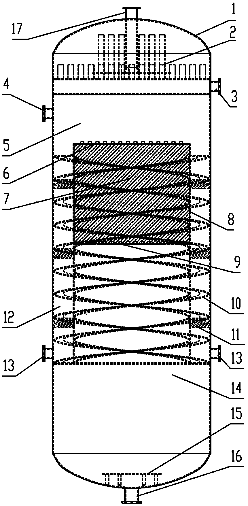
[0035] Depend on figure 1 It can be seen that the liquefied natural gas recondensation device provided by the present invention is a vertical structure, and from top to bottom, the outer cylinder 1, the LNG uniform distributor 2, the non-condensable gas discharge pipe 3, the BOG upper inlet pipe 4, the gas-liquid Mixing space 5, packing top plate 6, packing 7, inner cylinder 8, packing bottom plate 9, spiral lift gas plate 10, BOG uniform distribution plate 11, annular space 12, BOG bottom inlet pipe 13, LNG liquid phase space 14, vortex prevention Baffle plate 15, LNG outlet pipe 16.

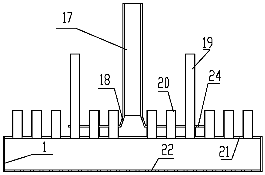
[0036] The LNG distributor 2 is arranged on the upper part of the outer cylinder 1, the upper end of the LNG inlet pipe 17 passes through the top of the outer cylinder 1 and is exposed outside the outer cylinder 1, and the non-condensable gas discharge pipe 3 is arranged on the primary...


PUM


Abstract

The invention discloses a liquefied natural gas re-condensation device. The device is mainly composed of an outer cylinder, an LNG uniform distributor, an inner cylinder and filler, and a gas-liquid mixing space is formed between the LNG uniform distributor and the inner cylinder; an opening in the upper end of the inner cylinder is welded to the inner wall of the outer cylinder through an annularouter folding edge at the lower end of the inner cylinder, an annular space is formed between the outer wall of the inner cylinder and the inner wall of the outer cylinder, the bottom of the annularspace is sealed, and the upper portion of the annular cylinder is communicated with the gas-liquid mixing space; a spiral gas lifting disc is arranged in the annular space, and the outer wall of the inner cylinder is sleeved with the spiral gas lifting disc; the spiral gas lifting disc enables the annular space to form a spiral gas lifting channel, and the lower end of the spiral gas lifting channel is communicated with a BOG bottom inlet pipe arranged at the bottom of the annular space; the upper end of the spiral gas lifting channel is communicated with the gas-liquid mixing space. The condensation efficiency of the re-condensation device is greatly improved through two times of condensation, and meanwhile, the operation stability and safety are improved.

Description

technical field [0001] The invention belongs to the technical field of liquefied natural gas (LNG) processing, in particular to a liquefied natural gas (LNG) recondensing device. Background technique [0002] The liquefied natural gas receiving station is the terminal link in the LNG industry chain. It receives liquefied natural gas from the LNG ship and transports it to downstream users after storage and regasification. In the receiving station system, due to pump operation, environmental heat leakage and unloading Displacement effects, cold insulation of equipment pipelines, etc. will cause the liquefied natural gas at extremely low temperature (-162°C) to vaporize to produce boil-off gas (BOG). [0003] The BOG recovery and treatment process at the LNG receiving station mainly includes direct compression and export, condensing into LNG through a recondenser, pressurization, gasification and export. The direct compression and export process requires downstream supporting l...

Claims


Application Information

Patent Timeline
Patent Type & Authority Applications(China)
IPC IPC(8): C10L3/10
CPCC10L3/10C10L2290/06C10L2290/56
Inventor 李战杰王以斌常征何建明王文昊何龙辉李津王惠勤杜富国
Owner LUOYANG PETROCHEMICAL ENG CORP SINOPEC
Why Eureka
Try Eureka