Rotary type forearm with hinge pin auxiliary stress mechanism

A pin shaft and protection mechanism technology, which is applied to mechanically driven excavators/dredgers, earth movers/shovelers, construction, etc., can solve the problems of pin shaft wear and tear, and achieve good rock breaking effect

Pending Publication Date: 2018-03-06
CHENGDU KAILONG MACHINERY MAINTENANCE
View PDF6 Cites 0 Cited by
  • Summary
  • Abstract
  • Description
  • Claims
  • Application Information

AI Technical Summary

Problems solved by technology

[0004] The purpose of the present invention is to provide a rotating small arm with a pin auxiliary force-receiving mechanism, which solves the problem that the mechanism used to connect with the digging hook on the existing digging hook rock arm has defects, and at the same time solves the angle change of the digging hook Finally, the wear of the pin shaft will become larger when breaking the rock

Method used


Image

  • Rotary type forearm with hinge pin auxiliary stress mechanism
  • Rotary type forearm with hinge pin auxiliary stress mechanism
  • Rotary type forearm with hinge pin auxiliary stress mechanism

Examples


specific Embodiment 1

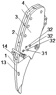
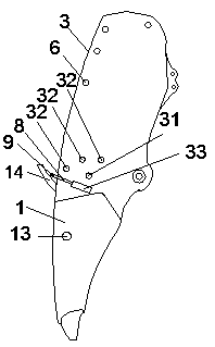
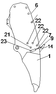
[0029] figure 1 , figure 2 , image 3 , Figure 4 , Figure 5 It shows a rotating small arm with a pin auxiliary force receiving mechanism, including an upper clamping part, a lower clamping hook part 1 and a pin shaft protection mechanism, and the upper clamping part includes left splints 2 arranged side by side and the right splint 3, there is a clamping gap 4 between the left splint 2 and the right splint 3, the upper part of the lower clip digging hook part 1 is snapped into the bottom of the clamping gap 4, and the bottom of the left splint 2 is provided with a left fixing channel. Hole 21 and left angle adjustment through hole 22, left angle adjustment through hole 22 has more than two, all left angle adjustment through holes 22 take left fixed through hole 21 as the circle center and surround left fixed through hole 21 equidistantly, right splint 3 The bottom of the bottom is provided with the right fixed through hole 31 that is arranged correspondingly with the le...

specific Embodiment 2

[0031] This embodiment further explains the connection mode between the left splint 2 and the right splint 3 on the basis of the specific embodiment 1. The left splint 2 and the right splint 3 are connected by one or more than one short column 6 , The stub 6 is arranged along the edges of the left splint 2 and the right splint 3 .

[0032] The left splint and the right splint are fixed and positioned with short posts.

specific Embodiment 3

[0033] This embodiment is based on the specific embodiment 1 to further illustrate the lower clip digging hook 1, the lower clip digging hook 1 is a hollow structure, and the middle part of the lower clip digging hook 1 is provided with Filling port 13, and the filling port 13 communicates with the inner cavity of the lower clip digging hook part 1.

[0034] The filling port is set to fill the hollow structure of the lower clamping piece with weight-increasing materials. In this way, different weights of filling materials can be filled in according to different situations to improve its rock-breaking effect.


PUM


Abstract

The invention discloses a rotary type forearm with a hinge pin auxiliary stress mechanism. The rotary type forearm with the hinge pin auxiliary stress mechanism comprises an upper clamping part, a lower clamping piece digging hook part and a hinge pin protection mechanism. The upper clamping part comprises a left clamping plate and a right clamping plate, and the lower clamping piece digging hookpart is arranged in the clamping clearance in a clamping manner. A left fixing through hole and left angle adjusting through holes are formed in the lower portion of the left clamping plate, and a right fixing through hole and right angle adjusting through holes are formed in the lower portion of the right clamping plate. A clamping piece fixing through hole and clamping piece angle adjusting through holes are formed in the upper portion of the lower clamping piece digging hook part. The left fixing through hole, the clamping piece fixing through hole and the right fixing through hole are connected by hinge pins; and the left angle adjusting through holes, the clamping piece angle adjusting through holes and the right angle adjusting through holes are connected by the hinge pins. The hingepin protection mechanism comprises a force transferring barb and the auxiliary stress mechanism. A hook groove of the force transferring barb presses against the auxiliary stress mechanism. Accordingto the rotary type forearm, the problem can be solved that defects exist in a mechanism, which is used for connecting with a digging hook, of a prior digging hook rock arm, and the problem can be solved at the same time that the hinge pins are high in mechanical wear.

Description

technical field [0001] The invention relates to the field of excavating equipment, in particular to a rotating small arm with a pin shaft auxiliary force receiving mechanism. Background technique [0002] The hook digging rock arm is usually used for digging and digging and planing the rock. The digging hook rock arm is composed of a large and small arm and a digging hook. The large and small arms can play a role in controlling the action of the digging hook. The big arm is connected with the frame, and the arm length is longer, so it is commonly called the big arm, and the small arm is connected with the digging hook, and the arm is small, so it is commonly called the small arm. [0003] The existing digging hook rock arm either adjusts the angle of the digging hook through the oil cylinder, or the digging hook is fixed, both of which have defects. The angle of the digging hook is adjusted through the oil cylinder. This structure occurs in rock breaking The reaction forc...

Claims


Application Information

Patent Timeline
Patent Type & Authority Applications(China)
IPC IPC(8): E02F3/36E02F3/38
CPCE02F3/3609E02F3/38
Inventor 刘楷
Owner CHENGDU KAILONG MACHINERY MAINTENANCE
Why Eureka
Try Eureka