Carbon dioxide rock breaking device and method for open-pit mine

A carbon dioxide and rock-breaking device technology, which is applied in open-pit mining, blasting, earthwork drilling and mining, etc., can solve the problems of difficulty in meeting the block size requirements of different ore and rock bodies, aggravating energy dissipation and dust pollution, and inability to carry out energy. , to achieve the effect of improving the grade of mineral resources, increasing the range and energy of rock breaking, and improving safety

Active Publication Date: 2021-04-16
NORTHEASTERN UNIV LIAONING
View PDF7 Cites 1 Cited by
  • Summary
  • Abstract
  • Description
  • Claims
  • Application Information

AI Technical Summary

Problems solved by technology

Traditional carbon dioxide blasting uses blasting cylinders for energy storage, which cannot be adjusted and controlled for energy, and it is difficult to meet the block size requirements of different ore bodies
In addition, due to the natural cracks in the hole wall of open-pit mine rock drilling, it will increase the dissipation channel of energy generated by gas phase change. At the same time, the traditional carbon dioxide blasting process does not use sealing treatment, which intensifies energy dissipation and generates dust pollution. As a result, the existing carbon dioxide blasting methods have shortcomings such as small rock breaking range and unsatisfactory rock breaking effect.

Method used


Image

  • Carbon dioxide rock breaking device and method for open-pit mine
  • Carbon dioxide rock breaking device and method for open-pit mine
  • Carbon dioxide rock breaking device and method for open-pit mine

Examples


Embodiment Construction

[0036] The present invention will be further described in detail below in conjunction with the accompanying drawings and specific embodiments.

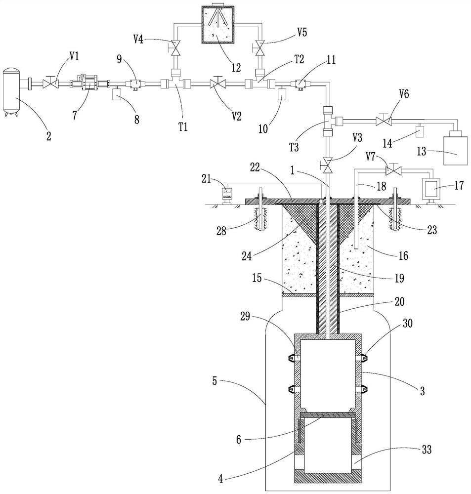
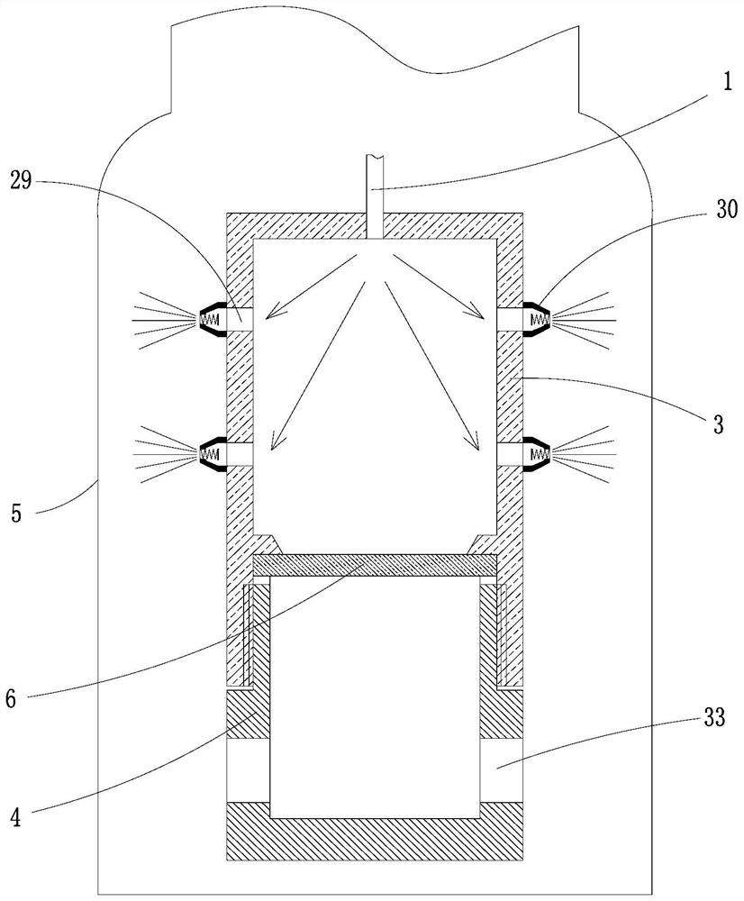
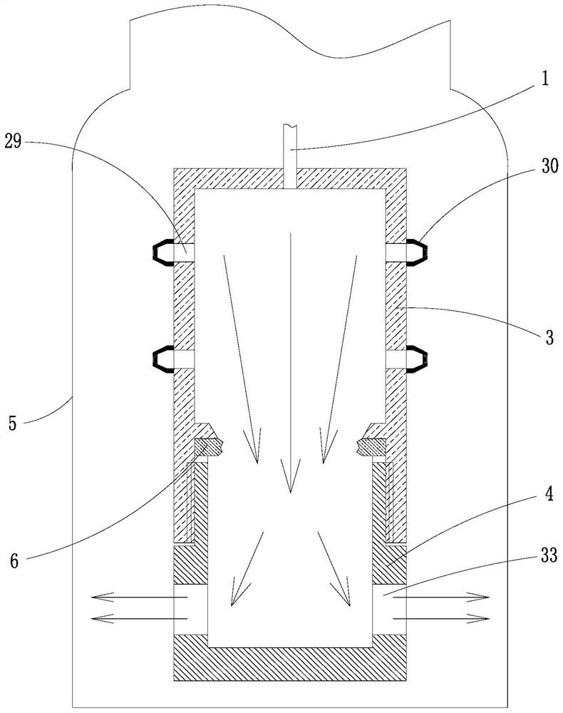
[0037] Such as Figure 1-6 As shown, a carbon dioxide rock-breaking device for open-pit mines includes a gas injection pipe 1, a liquid carbon dioxide storage tank 2, an energy storage chamber 3 and a fracturing chamber 4; the liquid carbon dioxide storage tank 2 is located outside the borehole 5, and the storage tank The energy chamber 3 and the fracturing chamber 4 are located inside the borehole 5; one end of the gas injection pipe 1 communicates with the liquid carbon dioxide storage tank 2, the other end of the gas injection pipe 1 communicates with the energy storage chamber 3, and the energy storage chamber 3 communicates with the The cracking chambers 4 are arranged in series, and the inner cavity of the energy storage chamber 3 and the cracking chamber 4 is separated by a sealing sheet 6 .

[0038] A first valve V1, a booste...


PUM


Abstract

The invention relates to a carbon dioxide rock breaking device and method for an open pit mine. The device comprises a gas injection pipe, a booster pump, a stirring type carbon dioxide and abrasive mixing mechanism, a liquid carbon dioxide storage tank, an energy storage chamber and a fracturing chamber, a packing sheet is arranged between the energy storage chamber and the fracturing chamber, and the gas injection pipe is provided with a pressure sensor, a flow sensor and a plurality of valves; and a ceramic electric heating sleeve and a thermal insulation sleeve are sequentially arranged on the portion, between the energy storage chamber and an opening of a drilled hole, of the gas injection pipe in a sleeving manner. The method comprises the following steps of distributing holes; determining rock breaking parameters; conducting hole drilling; performing thermal reaming on the drilled hole; sending an energy storage chamber and fracturing chamber series-connection body into the drilled hole; sealing the opening of the drilled hole; introducing carbon dioxide abrasive mixed fluid into an inner cavity of the energy storage chamber, and injecting liquid carbon dioxide while blocking cracks in the wall of the drilled hole; pressurizing and heating the liquid carbon dioxide to form supercritical carbon dioxide and seal the energy storage chamber; and continuously introducing supercritical carbon dioxide to break the packing sheet, enabling the liquid carbon dioxide in the drilled hole to be rapidly gasified and expanded, and enabling the energy of the liquid carbon dioxide to directly crack a rock stratum.

Description

technical field [0001] The invention belongs to the technical field of open-pit mining, in particular to a carbon dioxide rock-breaking device and method for open-pit mines. Background technique [0002] Open-pit mining is a process of removing the covering on the ore body to obtain the required minerals. It generally includes operations such as stripping, blasting, and mining. The blasting process is a key link that affects the quality, safety and economic benefits of ore body mining. The traditional blasting method is to use the blasting gas generated by the explosion of explosives in the borehole to achieve the purpose of cracking rocks. However, there are many safety hazards in the traditional blasting method. The explosives are easy to cause safety accidents during storage and transportation. It will cause a large air shock wave, which will not only bring noise and environmental pollution, but also a large seismic wave will affect the stability of the slope, which in tu...

Claims


Application Information

Patent Timeline
Patent Type & Authority Applications(China)
IPC IPC(8): F42D1/00F42D3/04F42D1/18E21C47/00
Inventor 李福栋陈天宇付彦吉郑旭孙子涵王文芳宋海国郝岩屿
Owner NORTHEASTERN UNIV LIAONING
Why Eureka
Try Eureka