Submersible electric pump control system and method

A technology of submersible electric pump and control system, applied in pump control, electrical components, electromechanical devices, etc., can solve the problems of inability to monitor and control the running state of submersible electric pump, meet the requirements of sealing and pressure bearing, and facilitate installation and disassembly Effect

Pending Publication Date: 2018-03-06
河北省机械科学研究设计院有限公司
View PDF0 Cites 2 Cited by
  • Summary
  • Abstract
  • Description
  • Claims
  • Application Information

AI Technical Summary

Problems solved by technology

[0004] The purpose of the embodiments of the present invention is to provide a submersible electric pump control system and its control method, aiming at solving the problem that the operating state of the submersible electric pump cannot be monitored and controlled. It adds a control mechanism on the basis of the submersible electric pump to realize the traditional Online Monitoring and Protection Control of Submersible Electric Pump

Method used


Image

  • Submersible electric pump control system and method
  • Submersible electric pump control system and method
  • Submersible electric pump control system and method

Examples


Embodiment 1

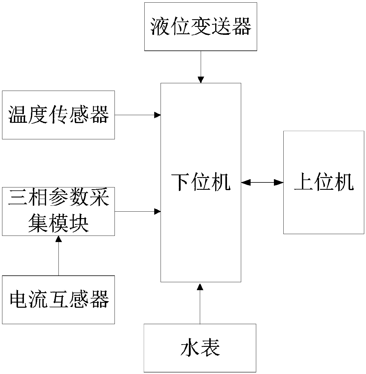
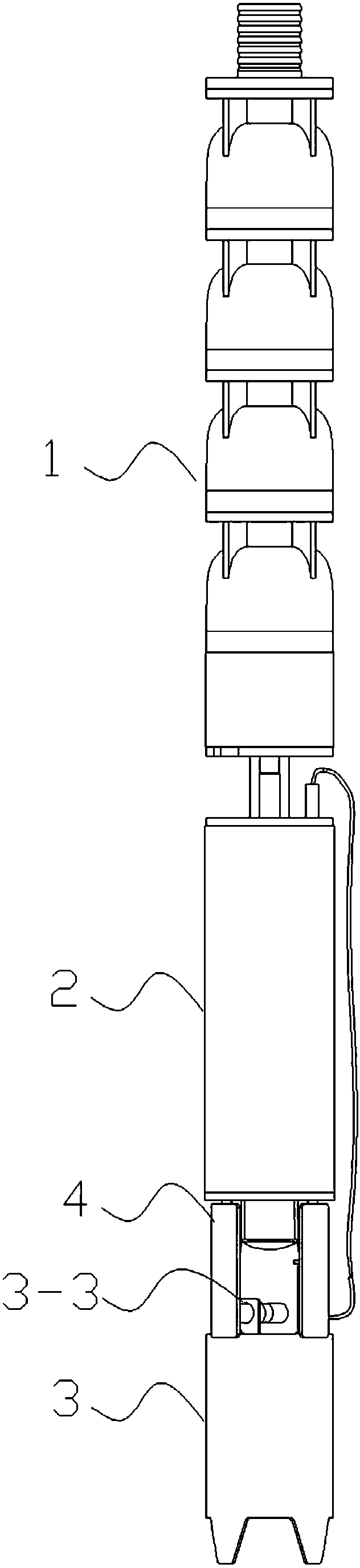
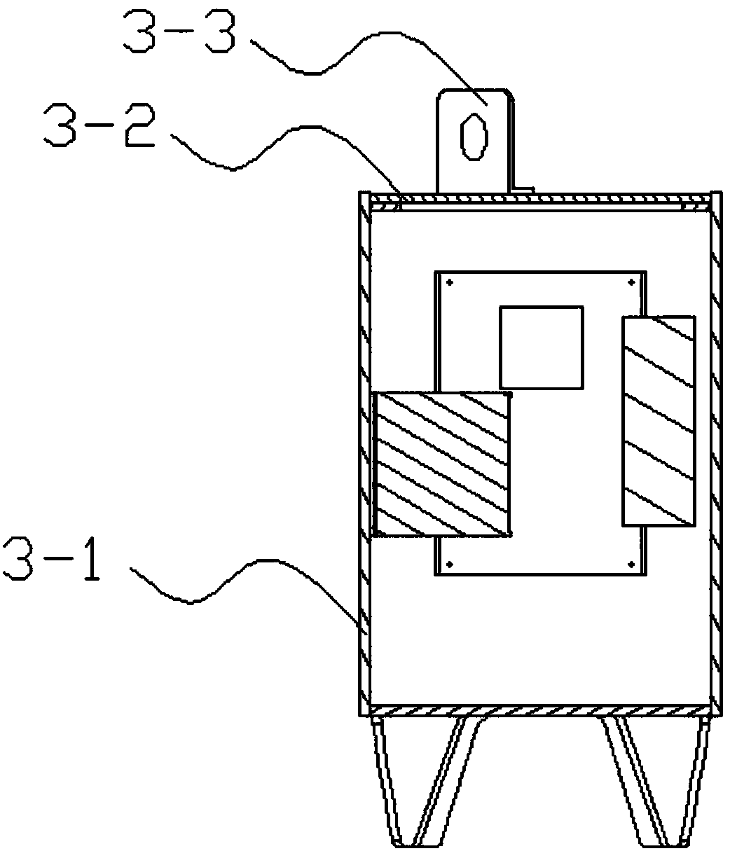
[0023] Please also refer to figure 1 and figure 2 , the submersible electric pump control system provided by the embodiment of the present invention will now be described. The submersible electric pump control system includes a motor 2, a pump body 1 arranged at the output end of the motor 2, a control mechanism 3 arranged at the base end of the motor 2, and a host computer arranged above the liquid level. The control mechanism 3 includes a waterproof sealed casing, a lower computer and a three-phase electrical parameter acquisition module and a power carrier module arranged in the cavity of the waterproof sealed casing, and also includes a liquid level transmitter arranged outside the waterproof sealed casing device, and a current transformer and a temperature sensor arranged in the motor housing. The output terminals of the liquid level transmitter, the temperature sensor and the three-phase electrical parameter acquisition module are respectively connected to the corresp...

Embodiment 2

[0039] An embodiment of the present invention provides a control method for a submersible electric pump, including the following steps:

[0040] The liquid level transmitter, temperature sensor and three-phase electrical parameter acquisition module collect the operating parameters of the submersible electric pump and transmit them to the lower computer; the operating parameters include the liquid level of the submersible electric pump, the temperature, current, voltage and power.

[0041] The lower computer controls the power carrier module to perform data modulation and loading on the collected working parameters, and uploads them to the upper computer in real time through power carrier communication.

[0042] The host computer compares the received parameters with corresponding thresholds, and when the parameters exceed the corresponding thresholds, it sends a disconnection command to the electromagnetic relay installed on the power line of the submersible electric pump.

...


PUM


Abstract

The invention discloses a submersible electric pump control system and a control method thereof, comprising a motor, a pump body provided with the output end of the motor, a control mechanism provided at the base end of the motor, and a host computer provided above the liquid surface. The control mechanism includes a waterproof sealed casing, a lower computer and a three-phase electrical parameter acquisition module and a power carrier module arranged in the cavity of the waterproof sealed casing, and also includes a liquid level transmitter and a device arranged outside the waterproof sealed casing. Current transformers and temperature sensors within the housing of the motor. The method is: the liquid level transmitter, the temperature sensor and the three-phase electrical parameter acquisition module collect the working parameters of the submersible electric pump and transmit them to the lower computer; the lower computer controls the power carrier module to perform data processing on the collected working parameters Modulation loading is uploaded to the host computer in real time by means of power carrier communication. The submersible electric pump control system and method realize online monitoring of the submersible electric pump.

Description

technical field [0001] The invention belongs to the technical field of submersible electric pumps, and in particular relates to a submersible electric pump control system and a control method thereof. Background technique [0002] The submersible electric pump is a kind of water pump in which both the impeller of the pump body and the motor driving the impeller are submerged in water. There are two types for deep wells and working surfaces. Among them, the submersible electric pump for deep well supplies power to the motor through the cable extending into the well, eliminating the need for a long transmission shaft, so it has a compact structure, light weight, and is easy to install, use and transfer. When it is working, the whole unit needs to be submerged into the water. Due to the long-term work underground, its operating status cannot be effectively monitored, resulting in high energy consumption in the water extraction process, high failure rates and repair rates, which...

Claims


Application Information

Patent Timeline
Patent Type & Authority Applications(China)
IPC IPC(8): F04D15/02H02K11/20H02K11/25H02K11/26H02K11/27
CPCF04D15/0281F04D15/0218H02K11/20H02K11/25H02K11/26H02K11/27
Inventor 吉明珠许志义周军吴海霞苏佩佩田杰宇
Owner 河北省机械科学研究设计院有限公司
Why Eureka
Try Eureka