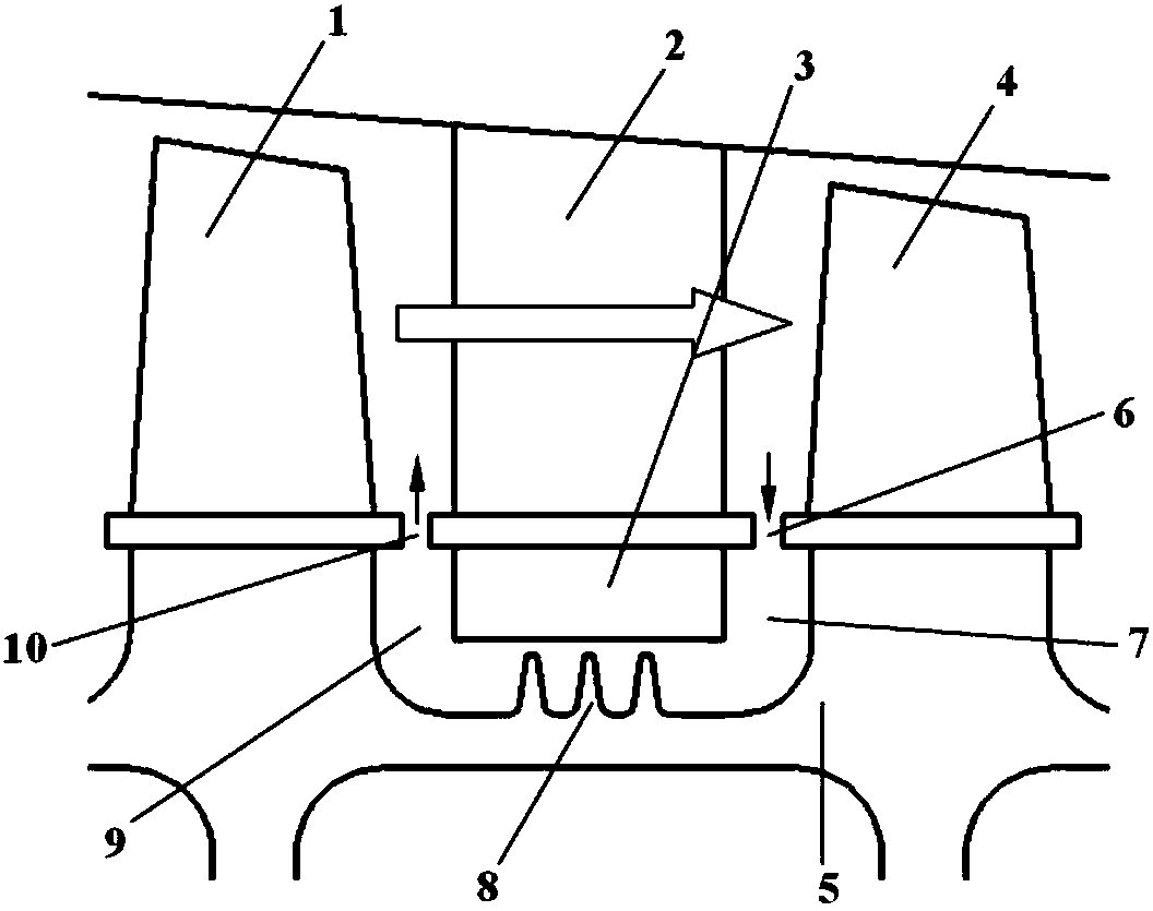
Dual radial sealing structure for compressor interstage
A compressor-stage, dual-stage technology, applied to components, mechanical equipment, machines/engines, etc. of elastic fluid pumping devices, can solve new problems such as reducing compressor life, inter-stage airflow temperature rise, and brush seals. Problems such as the difficulty in the application of the sealing structure to achieve the effect of reducing leakage flow and improving efficiency
- Summary
- Abstract
- Description
- Claims
- Application Information
AI Technical Summary
Problems solved by technology
Method used
Image

Examples
Embodiment
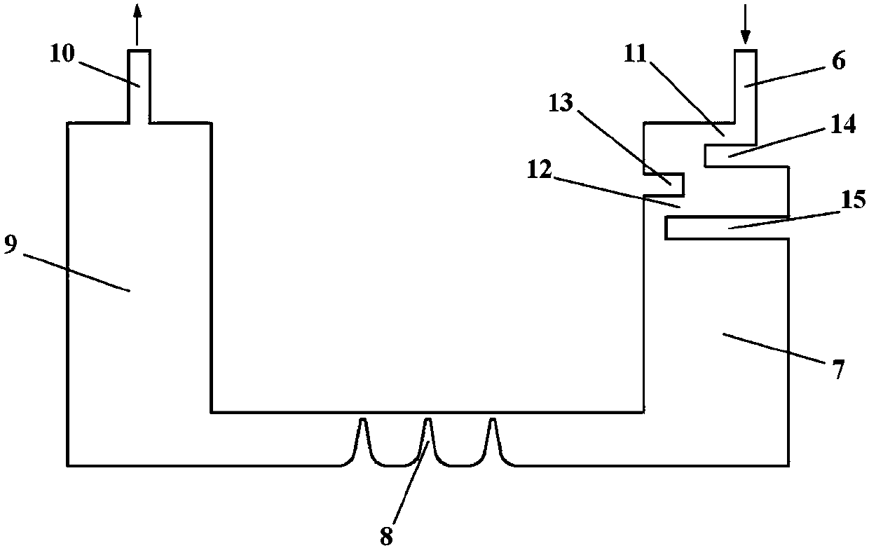
[0028] In this example, for a certain high-pressure compressor interstage structure, the difference in sealing performance between the conventional interstage structure and the interstage structure with double radial sealing is compared and analyzed.
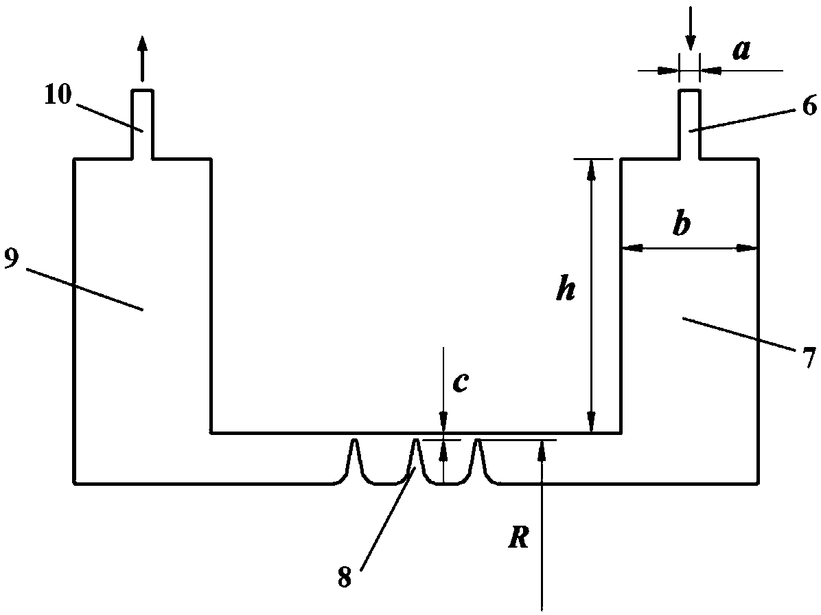
[0029] The geometric parameters of the interstage structure are as follows:
[0030] The axial sealing gap a of the inlet and outlet is 1.5mm, the width b of the inlet and outlet rotary disc cavity is 10mm, the height h of the inlet and outlet rotary disc cavity is 20mm, the clearance c of the tooth top of the grate tooth is 0.5mm, and the radius R of the tooth top is 250mm .
[0031] According to the CFD numerical simulation, it can be obtained that when the speed is 8000rpm, Figure 5 The conventional interstage structure velocity streamline diagram shown and Figure 6 Velocity streamline diagram of interstage structure with double radial seal shown. From Figure 5 It can be seen from the figure that in the conventional in...
PUM
 Abstract
Description
Claims
Application Information
 - R&D
- Intellectual Property
- Life Sciences
- Materials
- Tech Scout
- Unparalleled Data Quality
- Higher Quality Content
- 60% Fewer Hallucinations
Browse by: Latest US Patents, China's latest patents, Technical Efficacy Thesaurus, Application Domain, Technology Topic, Popular Technical Reports.
© 2025 PatSnap. All rights reserved.Legal|Privacy policy|Modern Slavery Act Transparency Statement|Sitemap|About US| Contact US: help@patsnap.com