
Device and method or detecting smoothness of laser track

A detection device and track detection technology, applied in measurement devices, optical devices, instruments, etc., can solve problems such as damage, affecting the efficiency of on-site inspection, and increasing deviation.

Pending Publication Date: 2018-03-06
王启华
View PDF0 Cites 11 Cited by
  • Summary
  • Abstract
  • Description
  • Claims
  • Application Information

AI Technical Summary

Problems solved by technology

The natural light intensity changes greatly in the field working environment. When the light spot is too bright and the environment is too dark, the eyes are prone to fatigue or injury. When the environment is too bright and the light spot is too weak, the recognition accuracy will be greatly reduced.
This situation greatly affects the actual detection accuracy, and at the same time significantly limits the extension of the current detection working distance
[0007] 2. The laser reference line currently used as the measurement reference, its stability will be affected by changes in laser parameters during the entire detection process, especially the jitter drift and slow bending of the light spot caused by atmospheric turbulence during transmission. As the detection distance increases, its The resulting deviation will increase dramatically
Obviously, the auxiliary light source will weaken the edge definition of the laser spot; as for the observation to determine whether the weather is stable and whether the spot jump is too large, as well as the conditions for judging whether the reference spot shifts too much during use and needs to be checked and retested, the calibration Whether the retest results after the nuclear test are more reliable than the previous results, all of which are difficult to implement relying on subjective and human processing
Moreover, these processing methods will also seriously affect the detection efficiency of the engineering site

Method used

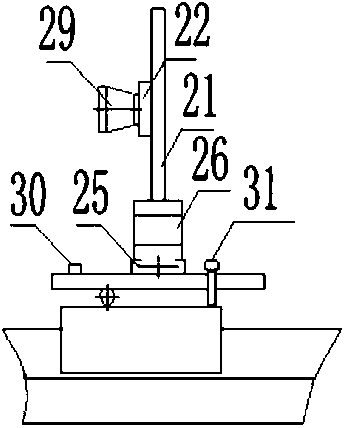
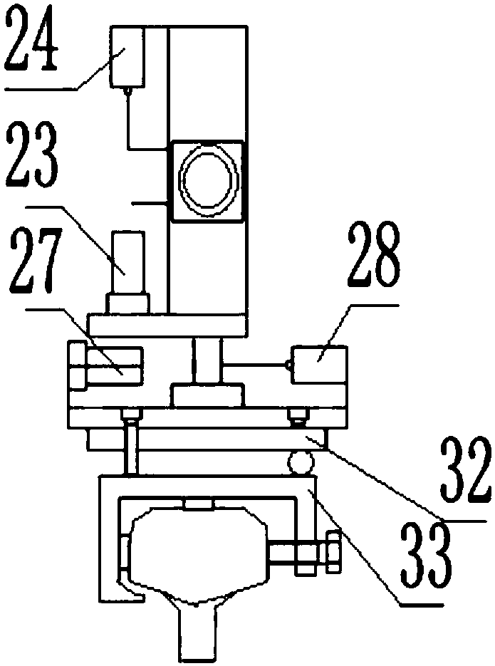
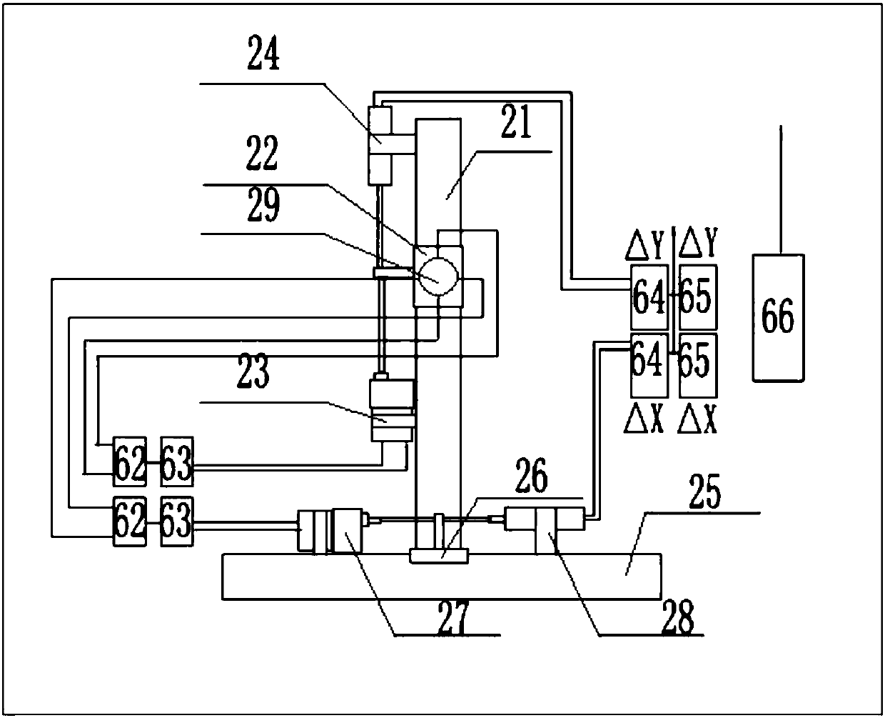

Image

  • Device and method or detecting smoothness of laser track
  • Device and method or detecting smoothness of laser track
  • Device and method or detecting smoothness of laser track

Examples


Embodiment Construction

[0061] In order to make the purpose, technical solutions and advantages of the embodiments of the present invention clearer, the technical solutions in the embodiments of the present invention will be clearly and completely described below in conjunction with the drawings in the embodiments of the present invention. Obviously, the described embodiments It is a part of embodiments of the present invention, but not all embodiments. Based on the embodiments of the present invention, all other embodiments obtained by persons of ordinary skill in the art without creative efforts fall within the protection scope of the present invention.

[0062] An embodiment of the present invention provides a laser track smoothness detection device, which includes: a laser emitter, a photoelectric positioning target and a photoelectric measurement target; the laser emitter is fixedly installed at the beginning of the track detection section, emits The collimated laser beam of the starting end det...


PUM


Abstract

The invention provides a device and method for detecting the smoothness of a laser track, and the method comprises the steps: detecting and obtaining a horizontal base measurement value Xi and a vertical base measurement value Y1 of a to-be-measured position Pi through a photoelectric measurement target; detecting a horizontal random deviation value delta(Xi) and a vertical random deviation valuedelta(Yi) of a laser reference beam through a deviation detection unit on the photoelectric measurement target, and correcting the horizontal random deviation value delta(Xi) and the vertical random deviation value delta(Yi); superposing the horizontal base measurement value Xi and a horizontal random deviation correction value delta(Xi)*Ki, and obtaining an engineering detection value Xi' in a horizontal direction; superposing the vertical base measurement value Yi and a vertical random deviation correction value delta(Yi)*Ki, and obtaining an engineering detection value Yi' in a vertical direction. The method solves a problem that the engineering detection result of a conventional laser smoothness detection device is low in precision and poor in reliability. The method is suitable for other laser alignment engineering measurement in an outdoor environment under the long-distance condition.

Description

technical field [0001] The invention relates to the technical field of laser alignment measurement, in particular to a laser track smoothness detection device and method. Background technique [0002] The direction and height of the railway track are two basic geometric parameters in the track smoothness inspection. Orbit direction refers to the lateral trend of the centerline of the track along the ground surface, whether it is straight on a straight line, and whether it is smooth on a curve. If the track direction is not smooth, it will cause the train to shake from side to side and snake, and thus increase the lateral impact force of the vehicle on the track, and further aggravate the irregularity of the track direction. The height refers to the longitudinal height difference of the top surface of the track. When the front and rear heights of the track are uneven, the train will experience bumps and impacts when passing these tracks. The above process can further aggrava...

Claims


Application Information

Patent Timeline
IPC IPC(8): G01B11/30
CPCG01B11/30
Inventor 王启华王东波王海波
Owner 王启华
Learn More