
CMOS power amplifier and temperature compensation circuit thereof

a technology of metal oxidesemiconductor and power amplifier, which is applied in the direction of amplifiers, amplifiers with semiconductor devices only, amplifiers with semiconductor devices, etc., can solve the problems of power amplifiers that cannot perform amplification in the optimal operating region, and the character of power amplifiers deteriorates

Active Publication Date: 2012-05-22
SAMSUNG ELECTRO MECHANICS CO LTD
View PDF10 Cites 7 Cited by
  • Summary
  • Abstract
  • Description
  • Claims
  • Application Information

AI Technical Summary

Benefits of technology

The solution enables CMOS power amplifiers to maintain constant characteristics and optimal amplification performance by compensating the gate bias voltage according to temperature variations, thereby ensuring stable operation regardless of temperature fluctuations.

Problems solved by technology

As a result, the characteristics of the power amplifier are deteriorated.
However, since temperature variations are not considered on the basis of an operating region of the power amplifier, the power amplifier cannot perform amplification in an optimal operating region.

Method used


Image

  • CMOS power amplifier and temperature compensation circuit thereof
  • CMOS power amplifier and temperature compensation circuit thereof
  • CMOS power amplifier and temperature compensation circuit thereof

Examples


Embodiment Construction

[0027]Exemplary embodiments of the present invention will now be described in detail with reference to the accompanying drawings.

[0028]The invention may, however, be embodied in many different forms and should not be construed as being limited to the embodiments set forth herein. Rather, these embodiments are provided so that this disclosure will be thorough and complete, and will fully convey the scope of the invention to those skilled in the art. In the drawings, the shapes and dimensions may be exaggerated for clarity, and the same reference numerals will be used throughout to designate the same or like components.

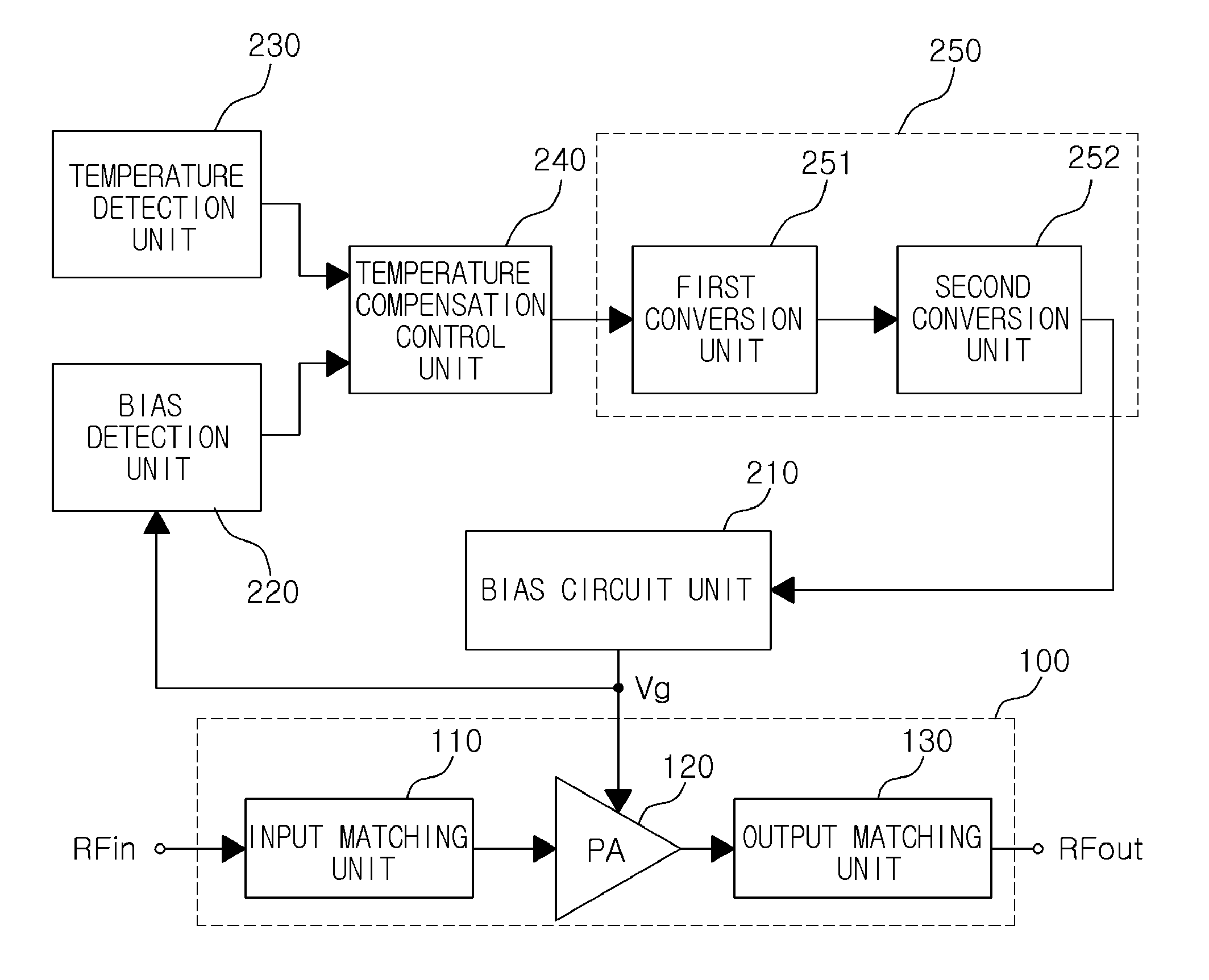
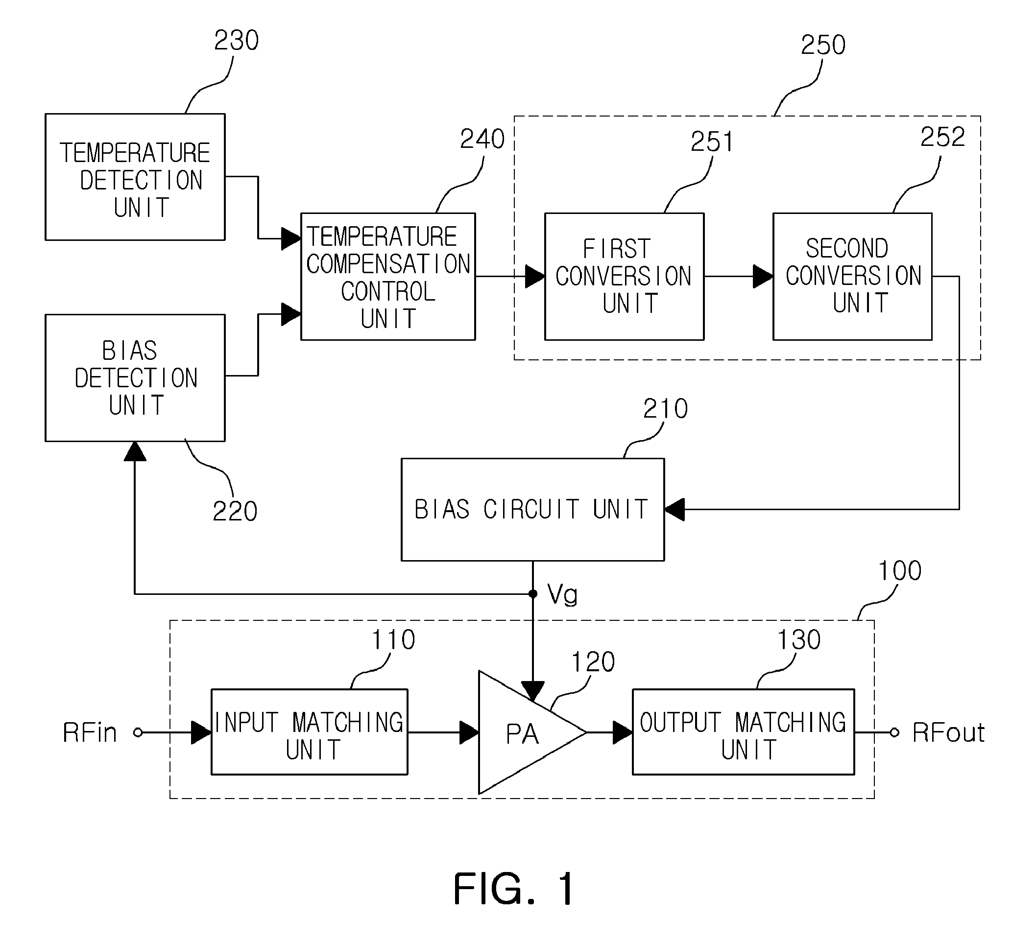
[0029]FIG. 1 is a block diagram illustrating a CMOS power amplifier according to an exemplary embodiment of the invention.

[0030]Referring to FIG. 1, a CMOS power amplifier according to an exemplary embodiment of the invention may include a power amplification circuit part 100, a bias circuit unit 210, a bias detection unit 220, a temperature detection unit 230, a temper...


PUM


Abstract

Disclosed is a CMOS power amplifier. A temperature compensation circuit of a CMOS power amplifier may include: a bias circuit unit supplying a gate bias voltage to a power amplification circuit part; a bias detection unit determining a class type of the power amplification circuit part according to the gate bias voltage; a temperature detection unit detecting a temperature-proportional voltage in proportion to ambient temperature; a temperature compensation control unit generating a compensation control value according to the temperature-proportion voltage in the class type determined by the bias detection unit; and a conversion unit converting the compensation control value of the temperature compensation control unit into a linear bias control value and providing the linear bias control value to the bias circuit unit, wherein the bias circuit unit compensates the gate bias voltage according to the linear bias control value of the conversion unit.

Description

CROSS-REFERENCE TO RELATED APPLICATIONS[0001]This application claims the priority of Korean Patent Application No. 10-2010-0055370 filed on Jun. 11, 2010, in the Korean Intellectual Property Office, the disclosure of which is incorporated herein by reference.BACKGROUND OF THE INVENTION[0002]1. Field of the Invention[0003]The present invention relates to a complementary metal-oxide-semiconductor (CMOS) power amplifier and a temperature compensation circuit thereof that can be applied to a mobile communications apparatus for mobile communications, and more particularly, to a CMOS power amplifier and a temperature compensation circuit thereof that perform temperature compensation on a gate bias voltage according to a class type of the CMOS power amplifier to thereby perform power amplification in a normal operating region, thereby maintaining constant characteristics regardless of temperature variations.[0004]2. Description of the Related Art[0005]In general, the operating characterist...

Claims


Application Information

Patent Timeline
Patent Type & Authority Patents(United States)
IPC IPC(8): H03F3/04
CPCH03F1/30H03F1/303H03F2200/447H03F2200/468
Inventor KIM, YOO HWANYOO, HYUN HWANNA, YOO SAMJO, BYEONG HAK
Owner SAMSUNG ELECTRO MECHANICS CO LTD
Learn More