Control method and apparatus for stabilizing optical wavelength

a control apparatus and optical wavelength technology, applied in the field of control apparatus and method for stabilizing optical wavelength, can solve the problems of wavelength monitor instability, laser damage or deterioration, etc., and achieve high precision optical wavelength stabilization and reduced circuitry scale

Inactive Publication Date: 2005-05-10
LUMENTUM JAPAN INC
View PDF10 Cites 8 Cited by
  • Summary
  • Abstract
  • Description
  • Claims
  • Application Information

AI Technical Summary

Benefits of technology

[0033]If the selectable control modes include a laser element constant temperature control mode and a wavelength monitoring control mode, wavelength can be stabilized with high precision in the short-term by selecting the laser element constant temperature control mode. In this case, as control is performed regardless of the laser output light, it is effective when power is switched on, when a stop signal is input or when there is a loss of signal in the transmission path after the coupler. On the other hand, by selecting the wavelength monitoring control mode, control operations are carried out depend on the wavelength fluctuation of the output light. Therefore, both wavelength fluctuations due to temperature variation of the laser element and wavelength fluctuations due to laser diode forward current variations are suppressed, and high precision optical wavelength stabilization is achieved in the

Problems solved by technology

As described heretofore, in the constant temperature control mode, there is a problem in that fluctuation of optical wavelength due to laser diode driving current variation cannot be compensated.
Further, in the control mode where the optical wave

Method used


Image

  • Control method and apparatus for stabilizing optical wavelength
  • Control method and apparatus for stabilizing optical wavelength
  • Control method and apparatus for stabilizing optical wavelength

Examples


first embodiment

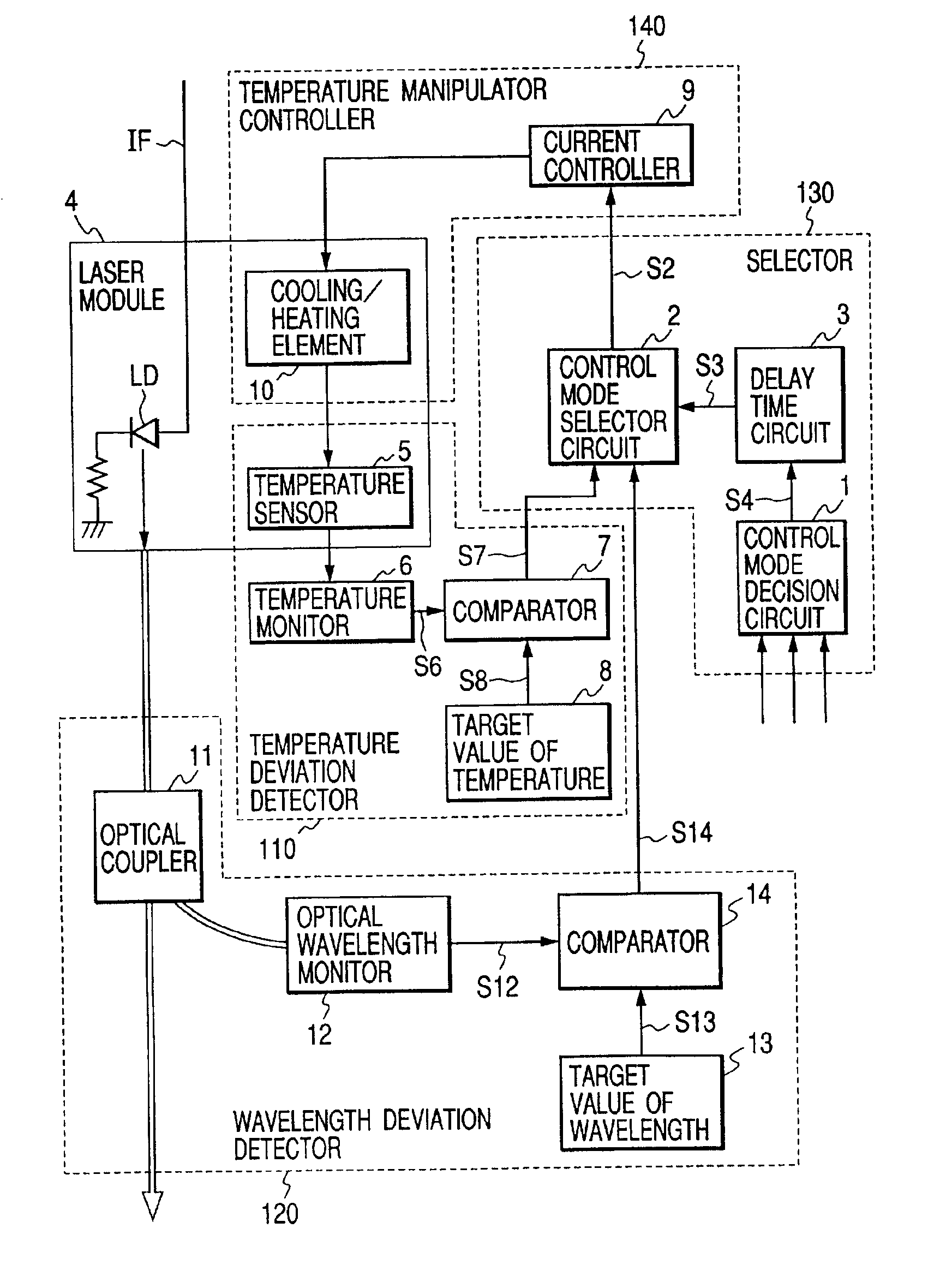
[0044]First, the invention will be described referring to FIGS. 5 and 6. According to this embodiment, two optical wavelength control circuits are provided with two different control modes, and a function is provided to select one of these modes according to external conditions.

[0045]The control apparatus for stabilizing optical wavelength shown in FIG. 5 comprises a temperature deviation detector 110 for detecting a deviation of laser temperature from a control target value, a wavelength deviation detector 120 for detecting a deviation of optical wavelength output by the laser from a control target value, a selector 130 for determining the control mode to be performed according to external conditions, and selecting the appropriate deviation detector for the determined control mode from either the temperature deviation detector 110 or the wavelength deviation detector 120, and a temperature manipulator controller 140 for controlling the laser temperature according to a deviation sig...

second embodiment

[0069]Next, this invention will be described referring to FIG. 7.

[0070]This embodiment differs from the first embodiment in that a constant forward current control mode is provided as one control mode instead of constant temperature control.

[0071]The control apparatus for stabilizing optical wavelength shown in FIG. 7 comprises a current deviation detector 210 which detects a deviation of laser diode driving current IF from a control target value and outputs the detected deviation as a deviation signal S16, a wavelength deviation detector 220 which detects a deviation of laser output light wavelength from a control target value and outputs the detected deviation as a deviation signal S14, a selector 230 which determines the control mode according to external conditions and selects either the deviation signal S16 from the current deviation detector 210 or the deviation signal S14 from the wavelength deviation detector 220, and a driving current controller 15 which controls the laser ...


PUM


Abstract

A control apparatus for stabilizing optical wavelength output by a laser module in which a laser element, temperature sensor and cooling/heating element are installed, comprises a temperature deviation detecting circuit comprising a temperature monitor for detecting a laser temperature, and a first comparator for outputting a first control signal indicating a difference between the laser temperature and a control target value, a wavelength deviation detecting circuit comprising a wavelength monitor for detecting light output from the laser element, and a second comparator for outputting a second control signal indicating a difference between the wavelength of the detected output light and a control target value, a selector circuit for selecting either of the detecting circuits according to the external conditions of the laser element, and a current controller for controlling the current supplied to the cooling/heating element based on the output signal from the selected detecting circuit.

Description

CROSS-REFERENCE TO RELATED APPLICATIONS[0001]The present application is a continuation of and is based on, and claims the benefit of priority from, Applicant's U.S. patent application Ser. No. 09 / 176,579, filed on Oct. 21, 1998, now issued as U.S. Pat. No. 6,212,210, which in turn claims the benefit of priority from Japanese Patent Appl. No. 9-292228 filed on Oct. 24, 1997, both of which are incorporated by reference herein as filly as if set forth in their entitety.BACKGROUND OF THE INVENTION[0002]1. Field of the Invention[0003]This invention relates to a control apparatus and method for stabilizing optical wavelength, and in particular a control apparatus and method for stabilizing optical wavelength which is suitable for use under any external conditions.[0004]2. Description of the Related Art[0005]In recent years, with the development of multimedia communications services, optical transmission systems which form the backbone of communications systems are moving to higher speeds ...

Claims


Application Information

Patent Timeline
IPC IPC(8): H01S5/0687H01S5/00H01S5/0683H01S5/068H04J14/00H04B10/07H04B10/2507H04B10/293H04B10/564H04B10/572H04J14/02
CPCH01S5/0687H01S5/06837
Inventor SERIZAWA, HIDEYUKI
Owner LUMENTUM JAPAN INC
Why Eureka
Try Eureka