Dual-optical-path laser marking apparatus and making method thereof

A technology of laser marking equipment and dual optical paths, applied in laser welding equipment, welding equipment, metal processing equipment, etc., can solve the problems of uncorrectable deviation, accumulated error, high cost of two-dimensional platform, etc., to ensure processing quality and improve production efficiency , the effect of easy operation

Active Publication Date: 2018-08-17
深圳市大族半导体装备科技有限公司
View PDF7 Cites 9 Cited by
  • Summary
  • Abstract
  • Description
  • Claims
  • Application Information

AI Technical Summary

Problems solved by technology

[0006] 1. Using a two-dimensional linear platform, the CCD moves twice after taking pictures, which is easy to cause cumulative errors;
[0007] 2. O

Method used


Image

  • Dual-optical-path laser marking apparatus and making method thereof
  • Dual-optical-path laser marking apparatus and making method thereof
  • Dual-optical-path laser marking apparatus and making method thereof

Examples


Embodiment Construction

[0045] The invention is a dual optical path laser marking equipment, which adopts picosecond laser, nanosecond laser, precise optical control system, various high-precision cylinders, and linear guide rails, and is equipped with customized light sources and industrial cameras at the same time. , so as to realize the positioning of the product sheet, implement picosecond laser for contour processing, and nanosecond laser to fill the interior of the contour to achieve a 2.5D etching effect on the stainless steel surface.

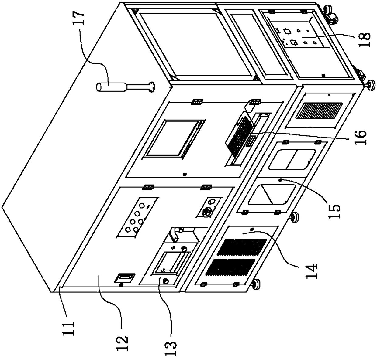
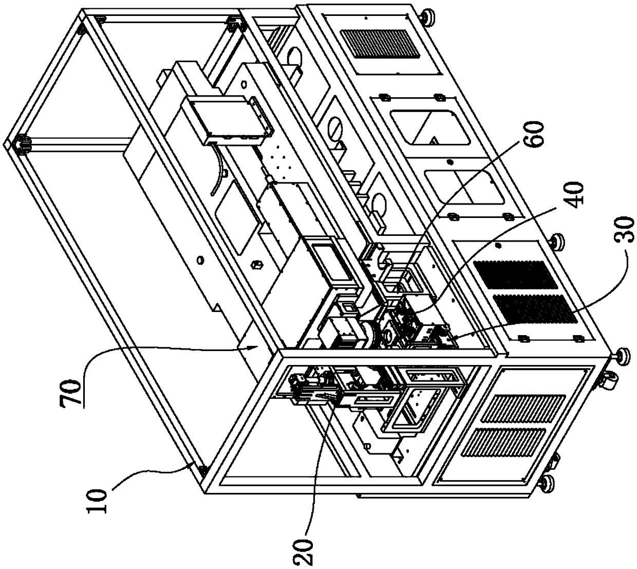
[0046] like figure 1 and figure 2 It is a schematic diagram of the structure of the dual optical path laser marking equipment. The dual optical path laser marking equipment includes a frame assembly 10, a camera assembly 20, a lifting table mechanism 30, a fixture assembly 40, a mirror assembly 60, an optical and galvanometer system 70, and Dust extraction structure 90 .

[0047] The frame assembly 10 is made of a frame welded by a 40mm square pass and is c...


PUM


Abstract

The invention provides a dual-optical-path laser marking apparatus and a making method thereof. The dual-optical-path laser marking apparatus comprises a rack assembly, a camera assembly, a lifting platform mechanism, a jig assembly, a mirror assembly and an optics and galvanometer system. The camera assembly is used for carrying out bias detection on optical paths. The jig assembly is fixed to the lifting platform mechanism. The optics and galvanometer system comprises a platform, an optical fiber nanosecond laser device and a picosecond laser device, an optical path system, a galvanometer and a field lens, wherein the optical fiber nanosecond laser device and the picosecond laser device are fixed to the platform, the optical path system is arranged in front of the optical fiber nanosecond laser device and the picosecond laser device, the galvanometer is connected with the optical path system, and the field lens is located below the galvanometer. Lasers respectively emitted by the optical fiber nanosecond laser device and the picosecond laser device pass through the optical path system, then enter the galvanometer in an incidence manner, and carry out laser processing on productsthrough the field lens. According to the dual-optical-path laser marking apparatus, the picosecond laser device is used for carrying out high-speed outline scanning on products, the nanosecond laser device is used for outline filling, the processing quality is effectively guaranteed, and the production efficiency is improved at the same time.

Description

technical field [0001] The invention relates to the field of laser processing, in particular to a dual optical path laser marking device and a marking method thereof. Background technique [0002] In the consumer electronics industry, more and more products need to be marked with LOGO or serial number somewhere after assembly, as a transmission of corporate image and a key element of product quality. [0003] For example, the laser marking equipment marks the surface of a certain brand of wearable products on stainless steel. Depth processing with ultra-fast laser. In the laser marking process, since the picosecond laser photons directly destroy the structural bonds of the target material, this is relatively a "cold" processing with a small heat-affected area, and the entire processing process is very clean without recasting the material. As a surface treatment, nanosecond laser has a certain heat-affected zone, which can frequently recast materials and micro-process the p...

Claims


Application Information

Patent Timeline
IPC IPC(8): B23K26/00B23K26/70B23K26/08B23K26/03B23K26/0622B23K26/067
CPCB23K26/00B23K26/032B23K26/0624B23K26/067B23K26/0853B23K26/702
Inventor 江军欧明辉曾威尹建刚高云峰
Owner 深圳市大族半导体装备科技有限公司
Why Eureka
Try Eureka