A kind of bidirectional stress fatigue test device and test method

A fatigue test, bidirectional stress technology, applied in measuring devices, using repetitive force/pulse force to test the strength of materials, instruments, etc., can solve the problems of difficult topology design, high equipment manufacturing cost, high noise, etc., to reduce hardware The effect of purchasing cost, reducing test cost, and reducing manufacturing cost

Active Publication Date: 2019-07-09
AVIC BEIJING AERONAUTICAL MFG TECH RES INST
View PDF8 Cites 0 Cited by
  • Summary
  • Abstract
  • Description
  • Claims
  • Application Information

AI Technical Summary

Problems solved by technology

For the cross-shaped test piece, a specific shape is usually designed in the cross area of ​​the test piece to generate axial-axial stress, the load is transmitted through the clamp connected to the four points of the test piece, and the load is applied by a hydraulic testing machine; for The shape of the cylindrical notched test piece is usually uniaxial axial loading, and the stress in two directions is controlled by the shape of the notch. The existing test technology has the following deficiencies: the shape of the cross-shaped fatigue test piece usually needs to design a high-order curve Transition section, in order to ensure that the assessment part of the cross point is in an axial-axial two-dimensional tensile stress state, the topology design is difficult and the cycle is long; the shape of the fatigue test piece is cross-shaped, the shape of the assessment area is complex, and the test piece is processed It is very difficult and requires high-precision CNC machine tools in order to process the test section with a qualified shape, and the manufacturing cost of a single piece is high; for the cross-shaped fatigue test piece, the four points of the test piece are rigidly connected to the testing machine. Deformation occurs after loading. In order to make the shape after deformation similar to that before deformation and avoid additional bending moments, only four actuators can be used, and the actuators need to be controlled in a coordinated manner. The control accuracy is high, the test equipment is complicated, and the test cost is high. ; For the cross-shaped fatigue test piece, in order to accurately control the applied load, only hydraulic controllers can be used in the test equipment, and the loading frequency is limited, usually not higher than 30Hz. Only low-cycle fatigue tests can be carried out, and the equipment manufacturing cost High, the noise is large during the working process of the equipment; the fatigue test piece with a cross-shaped shape has poor compression stability, and usually only tensile loads can be applied, that is, the stress ratio on the test piece can only be selected between 0.1 and 1.0; The shape of the test piece is a solid notched cylindrical test piece, and stress concentration occurs at the notch, resulting in a gradient in the stress distribution of the assessment section, which is not convenient for later analysis; the shape is a solid notched cylindrical test piece, and the stresses in the two directions of the assessment area are coupled with each other, that is, only Ability to carry out axial stress fatigue tests with the same phase and same frequency, and the test types are limited
[0006] To sum up, in the current existing technology, although the low-cycle fatigue test and two-way fatigue test technology are relatively perfect, and there are many controllable loading parameters, the shape of the test piece is complicated, the design of the test piece is difficult, the test equipment is complicated, and the test cost is high. ; High cycle fatigue test and two-way fatigue test can control less loading parameters and stress states, and the stress distribution of the assessment part is complicated
In addition, in the current two-way fatigue test, there is a mutual coupling phenomenon in the application of loads in two directions, which is the root cause of the difficulty of the two-way fatigue test

Method used


Image

  • A kind of bidirectional stress fatigue test device and test method
  • A kind of bidirectional stress fatigue test device and test method
  • A kind of bidirectional stress fatigue test device and test method

Examples


Embodiment 1

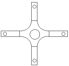
[0031] like Figure 3-5As shown, a two-way stress fatigue test device includes a test fixture 1, the two ends of the test fixture 1 are respectively connected with a clamping device, and the clamping device includes stop screws 2 respectively connected to the two ends of the test fixture 1, and the stop screw 2 is connected to the two ends of the test fixture 1. The other ends of the moving screws 2 are respectively connected with adapter joints 4, and a sealing ring 13 is arranged at the connection between the end of the test fixture 1 and the stop screw 2, and an upper sealing block 15 is connected to the outside of the sealing ring 13 at one end, and the upper The other end of the sealing block 15 is connected with a sealing top block 14, the outside of the sealing ring 13 at the other end is connected with a lower sealing block 3, and the other end of the lower sealing block 3 is also connected with a sealing top block 14, a clamping device and a test fixture 1 A detonatio...

Embodiment 2

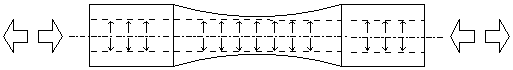
[0033] like Figure 3-5 As shown, a test method of a bidirectional stress fatigue test device includes an axial load application method and a circumferential load application method, and the axial load application method is to fix the test device in the electromagnetic high cycle fatigue test through an adapter 4 On the machine chuck, when the electromagnetic high cycle fatigue testing machine stretches the adapter 4, the tensile load transmits the load to the examination part of the test fixture 1 through the matching thread between the adapter 4 and the test fixture 1. When the electromagnetic high cycle fatigue testing machine compresses the adapter 4, the compressive load is transmitted to the stop screw 2 through the adapter 4, and the stop screw 2 transmits the compressive load through the matching thread with the test fixture 1 On the examination part of the upper test fixture 1, by controlling the magnitude of the load, the condition of the stress ratio of the examinat...


PUM


Abstract

The invention relates to a bidirectional stress fatigue test apparatus, which comprises a tested clamping member, wherein both ends of the tested clamping member are respectively connected to a clamping device, the clamping devices are connected to a circumferential load loading device, the clamping devices comprise stopping bolts respectively connected to both ends of the tested clamping member,the other ends of the stopping bolts are respectively connected to a switching joint, the connection position of the end portion of the tested clamping member and the stopping bolt is provided with asealing ring, the outer portion of the sealing ring on one end is connected to an upper sealing block, the other end of the upper sealing block is connected to a sealing ejection block, the outer portion of the sealing ring on the other end is connected to a lower sealing block, the other end of the lower sealing block is connected to a sealing ejection block, and the center of the clamping devices and the tested clamping member are provided with an explosion reduction rod axially extending along the long axis of the tested clamping member. The test method of the bidirectional stress fatigue test apparatus comprises an axial load application method and a circumferential load application method. With the technical scheme of the present invention, the independent force transfer of the loadedforce transfer channel and the sealed force transfer channel is achieved, and the sealing performance of the structure is improved.

Description

technical field [0001] The invention relates to the technical field of mechanical performance testing devices and methods, in particular to a two-way stress fatigue testing device and testing method. Background technique [0002] Structural design is an essential link in the product development process. It realizes reasonable stress distribution by selecting the best topological parameters to avoid abnormal damage of mechanical components during normal operation. The basic idea is to adjust the distribution of stress under typical load conditions by changing the topological characteristics, so that the real stress inside the structure is lower than the ability of the material to resist such stress (hereinafter referred to as material performance). There are two main sources of stress: One type is the load imposed by the external environment during the working process, such as uneven ground, impact of foreign objects, etc.; the other type is the stress generated during the pr...

Claims


Application Information

Patent Timeline
Patent Type & Authority Patents(China)
IPC IPC(8): G01N3/36G01N3/04
CPCG01N3/04G01N3/36
Inventor 邓瑛李志强
Owner AVIC BEIJING AERONAUTICAL MFG TECH RES INST
Why Eureka
Try Eureka