

Resonant converter and current processing method
A technology of resonant converter and resonant circuit, which is applied in the field of communication to achieve the effect of ensuring efficiency and power density and simplifying the control method
- Summary
- Abstract
- Description
- Claims
- Application Information
AI Technical Summary
Problems solved by technology
Method used
Image

Examples
Embodiment 1
[0025] In this embodiment, a resonant converter is provided. The resonant converter is composed of two or more resonant units, and the driving signals between the resonant units are staggered by a certain angle to achieve the effect of reducing the ripple current. The resonant converter not only has high efficiency, but also can realize current sharing and power balance between resonant units.
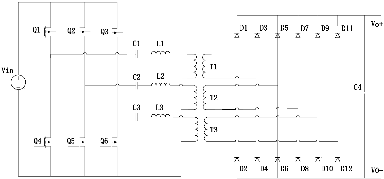
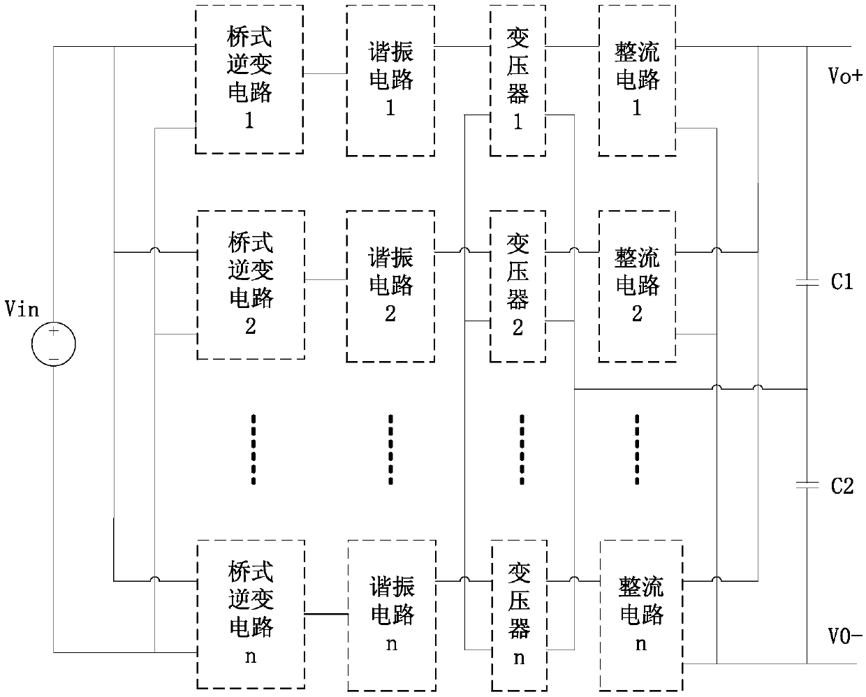
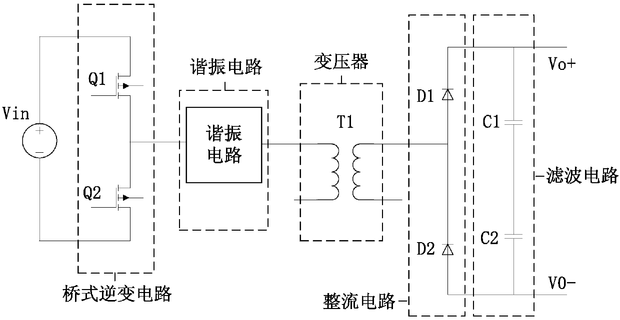
[0026] figure 2 is a schematic structural diagram of a resonant converter according to an embodiment of the present invention, such as figure 2 As shown, the resonant converter includes more than two resonant units, and each resonant unit includes: a bridge inverter circuit, a resonant circuit, a transformer, a rectifier circuit, a filter circuit; the input terminal of the bridge inverter circuit and the input of DC voltage The output terminal of the bridge inverter circuit is connected to the input terminal of the resonant circuit (for example, the two ends of the bridge inverter c...
Embodiment 2
[0043] In this embodiment, a current processing method is also provided, Image 6 is a flowchart of a current processing method according to an embodiment of the present invention, such as Image 6 As shown, the method includes:
[0044] Step S602, through the second input terminals of the transformer primary sides of the two or more resonant units of the resonant converter being connected in a polygonal connection or a star connection and the connection points of the transformer primary sides of the two or more resonant units being in a suspended state, Make the current amplitudes of the transformer primary sides of the two or more resonant units equal, wherein the two or more resonant units are staggered by a predetermined angle.
[0045] Through the above steps, since the second input ends of the transformer primary sides of more than two resonant units are delta-shaped or star-shaped connected, and the transformer primary sides of more than two resonant units are suspende...
PUM
 Abstract
Description
Claims
Application Information