
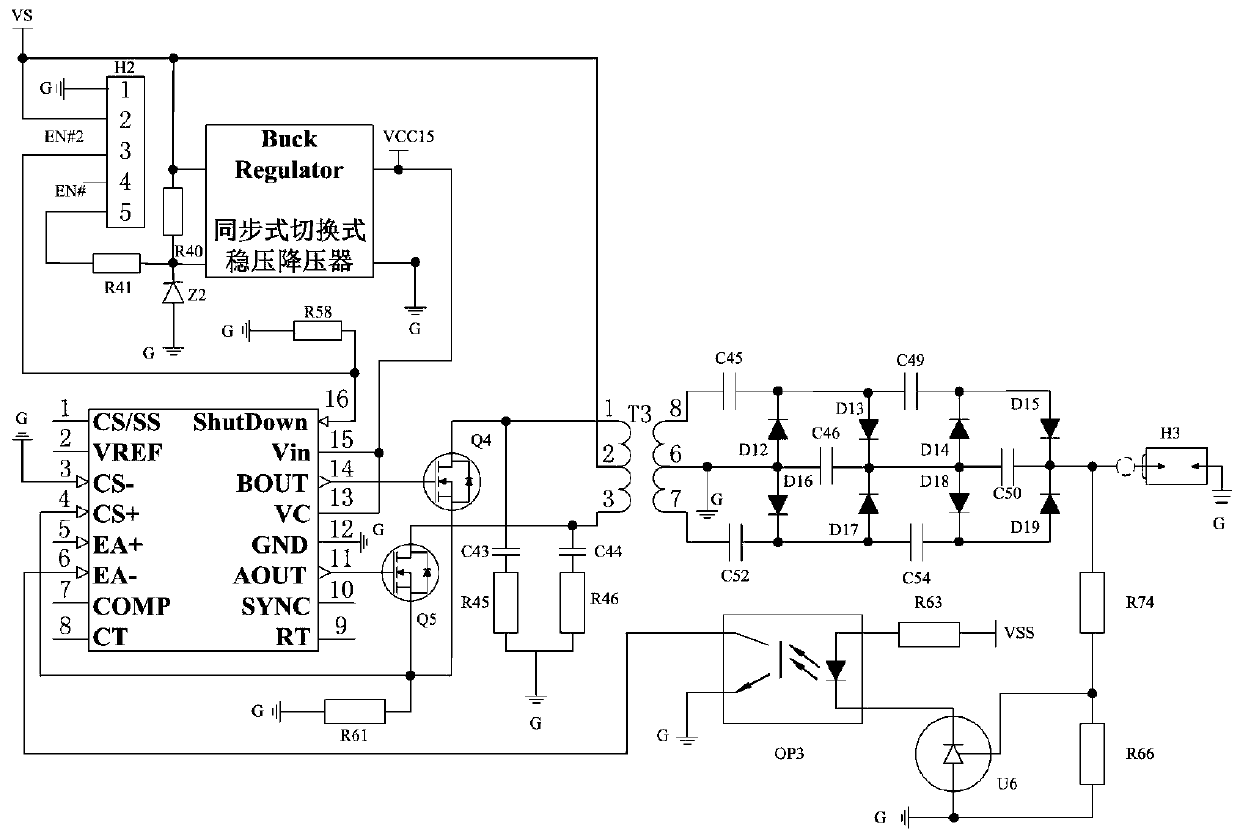
A Charging Circuit for Micro Pulse Plasma Thruster

A pulsed plasma and charging circuit technology, applied in battery circuit devices, circuit devices, instruments, etc., can solve the problems of low utilization rate of transformer magnetic core, unstable output voltage, large ripple coefficient, etc.

Active Publication Date: 2019-10-29
NAT UNIV OF DEFENSE TECH
View PDF6 Cites 1 Cited by
  • Summary
  • Abstract
  • Description
  • Claims
  • Application Information

AI Technical Summary

Problems solved by technology

[0011] Based on this, it is necessary for the present invention to provide a charging circuit for a micro-pulse plasma thruster, aiming at poor reliability of the charging circuit, unstable output voltage, high withstand voltage of the power tube, low utilization rate of the transformer magnetic core, and The wave coefficient is large, there are technical problems such as power consumption during standby, and the charging circuit for the micro-pulse plasma thruster provided by the present invention has better reliability, stable voltage output, lower power tube withstand voltage, and improved transformer core utilization. , The ripple coefficient is reduced, and there is no power consumption during standby

Method used


Image

  • A Charging Circuit for Micro Pulse Plasma Thruster

Examples


Embodiment Construction

[0022] In order to make the object, technical solution and advantages of the present invention clearer, the present invention will be further described in detail below in conjunction with the accompanying drawings and specific implementation methods. It should be understood that the specific embodiments described here are only used to explain the present invention, and do not limit the protection scope of the present invention.

[0023] It should be noted that when an element is referred to as being “fixed on”, “disposed on” or “installed on” another element, it may be directly on the other element or there may be an intervening element. When an element is considered to be "connected" to another element, it may be directly connected to the other element or there may be an intervening element at the same time; the specific way that one element is fixedly connected to another element can be realized through existing technologies, and will not be discussed here. To repeat it agai...


PUM


Abstract

The invention provides a charging circuit for a micro-pulse plasma thruster. The charging circuit comprises a power conversion circuit, a rectifying and filtering circuit and a PWM controller circuit;the power conversion circuit is used for converting a satellite-borne power supply (VS) into high-voltage pulses; the rectifying and filtering circuit is used for filtering and rectifying the high-voltage pulses output by the power conversion circuit to obtain required direct-current voltage; the power conversion circuit further comprises a transformer (T3); the satellite-borne power supply (VS)is connected with a primary coil of the transformer (T3), and a secondary coil of the transformer (T3) is connected with the rectifying and filtering circuit and used as a high-voltage pulse power supply. The charging circuit for the micro-pulse plasma thruster is good in reliability, voltage-stabilized output is achieved, the bearing voltage of a power tube is reduced, the utilization rate of a magnetic core of the transformer is increased, the ripple coefficient is reduced, and the electric energy consumption is avoided during standby.

Description

technical field [0001] The invention relates to a charging circuit for a micro-pulse plasma thruster. Background technique [0002] At present, the rapid development of satellite systems along the network and miniaturization makes it necessary to develop micro-electric thrusters that can meet the high-precision attitude control requirements of micro-nano satellites, and have the characteristics of light weight, small size, and low power consumption. Micro-Pulsed Plasma Thruster (μPPT) is a kind of Pulsed Plasma Thruster (PPT). Usually, the PPT whose system mass is less than 1kg is called μPPT. Its mass, volume and The power consumption is at least an order of magnitude lower than that of PPT. In addition to the advantages of traditional PPT, such as high thrust density, high specific impulse, small and precise thrust, high control precision, simple structure, and high reliability, μPPT also has the advantages of low power consumption, low cost, light weight, and small size....

Claims


Application Information

Patent Timeline
Patent Type & Authority Patents(China)
IPC IPC(8): H02M3/337H02M1/14H02J7/00
CPCH02J7/00H02J2207/20H02M1/14H02M3/337Y02B70/10
Inventor 何兆福吴建军何振程玉强黄强张宇李健欧阳
Owner NAT UNIV OF DEFENSE TECH
Learn More