Cooking utensil

A technology for cooking utensils and heaters, which is applied to cooking utensils, cooker shells/covers, household appliances, etc., and can solve the problems of inner pots without handles, etc.

Pending Publication Date: 2018-03-09
ZHEJIANG SHAOXING SUPOR DOMESTIC ELECTRICAL APPLIANCE CO LTD
View PDF0 Cites 61 Cited by
  • Summary
  • Abstract
  • Description
  • Claims
  • Application Information

AI Technical Summary

Problems solved by technology

[0005] The main purpose of the present invention is to provide a cooking utensil to solve the problem in the prior art th

Method used


Image

  • Cooking utensil
  • Cooking utensil
  • Cooking utensil

Examples


Embodiment 1

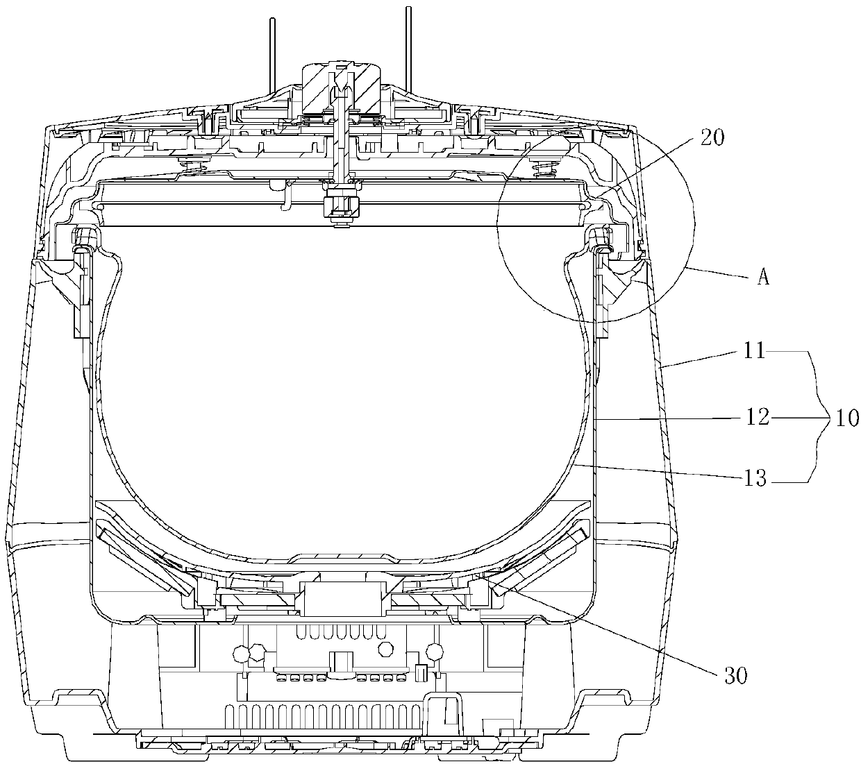
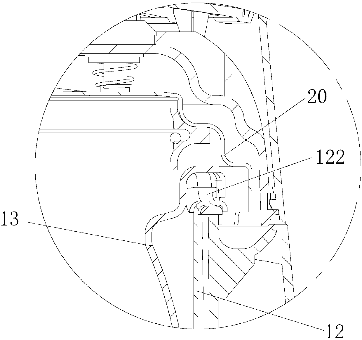
[0028] figure 1 A schematic cross-sectional view of Embodiment 1 of the cooking utensil according to the present invention is shown. Such as figure 1 As shown, the cooking appliance of the first embodiment includes: a pot body 10 , a pot cover 20 and a heating device 30 . Wherein, the pot body 10 includes an outer shell 11 arranged sequentially from outside to inside, a heat preservation cover 12 and an inner pot 13 arranged inside the heat preservation cover 12. Support the pot edge of inner pot 13. The pot cover 20 is provided on the pot body 10, and the pot cover 20 is provided with an opening structure. The heating device 30 is disposed in the outer casing 11 and located below the inner pot 13 , and there is a predetermined distance between the heating device 30 and the inner pot 13 .

Embodiment 2

[0042] Figure 4 A schematic cross-sectional view of Embodiment 2 of the cooking utensil according to the present invention is shown. Such as Figure 4As shown, the cooking appliance of the second embodiment includes: a pot body 10 , a supporting structure, a pot cover 20 and a heating device 30 . Wherein, the pot body 10 includes an outer shell 11 , a heat preservation cover 12 , and an inner pot 13 arranged inside the heat preservation cover 12 sequentially arranged from outside to inside. The inner pot 13 is used to contain the food to be cooked, and the mouth of the heat preservation cover 12 is provided with a plurality of pot teeth. The support structure is located between the mouth of the heat preservation cover 12 and the edge of the inner pot 13 , and the mouth of the heat preservation cover 12 abuts against the edge of the inner pot 13 through the support structure. The pot cover 20 is provided on the pot body 10 . The heating device 30 is disposed in the outer s...

Embodiment 3

[0056] Figure 7 A schematic cross-sectional view of Embodiment 3 of the cooking utensil according to the present invention is shown. Such as Figure 7 As shown, the cooking utensil of the third embodiment includes: a pot body 10 , a pot cover 20 and a heating device 30 . Wherein, the pot body 10 includes an outer shell 11 arranged in sequence from outside to inside, a heat preservation cover 12 and an inner pot 13 arranged inside the heat preservation cover 12. The inner pot 13 is used to hold the food to be cooked, and the lower end of the heat preservation cover 12 is provided with a part 14, the support part 14 abuts against and supports the lower part of the inner pot 13. The pot cover 20 is provided on the pot body 10 . The heating device 30 is disposed in the outer shell 11 and is located below the inner pot 13 with a predetermined distance from the inner pot 13 .


PUM


Abstract

The invention provides a cooking utensil. The cooking utensil includes a pot body, a pot cover, and a heating device; the pot body includes a shell, a thermal insulation cover and an inner pot body arranged from outside to inside in sequence, wherein the inner pot body is arranged in the thermal insulation cover; the inner pot body is used for containing cooked food, and an opening of the thermalinsulation cover is abutted to the edge of the inner pot body for supporting; the pot cover is arranged on the pot body, the heating device is arranged in the shell and located below the inner pot body, and a preset distance is left between the heating device and the inner pot body. According to the technical scheme, the problem that in the prior art, an electric pressure cooker with the inner potbody not provided with a handle needs a heating disk for supporting the inner pot body is solved.

Description

technical field [0001] The present invention relates to cooking utensils, in particular to an improvement in the way of supporting the inner pot of the cooking utensils. Background technique [0002] In the prior art, the electric pressure cooker is heated by a heating plate or by IH. The heating plate structure can withstand the pressure of the inner pot, while the coil plate of the IH structure needs to keep a certain distance from the inner pot and cannot bear pressure. [0003] The inner pot of some electric pressure cookers has a handle. This type of electric pressure cooker buckles the inner pot through the pot cover. The handle of the inner pot is supported on the middle plate. When pressing up, the middle plate can limit the sinking of the inner pot. This type of electric pressure cooker can be heated by heating plate or by IH. However, this structure has requirements on the thickness of the inner pot, and the inner pot needs incisors, the process is complicated an...

Claims


Application Information

Patent Timeline
IPC IPC(8): A47J27/086A47J36/36A47J36/24
CPCA47J27/086A47J36/2483A47J36/36
Inventor 何国营孟城城丁金炬王正清李爱良
Owner ZHEJIANG SHAOXING SUPOR DOMESTIC ELECTRICAL APPLIANCE CO LTD
Why Eureka
Try Eureka