
Drum-type filtering device

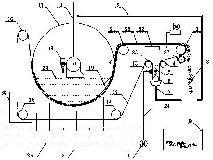
A filter device and drum-type technology, which is used in the precision filtration of cutting fluid in the field of machine tool processing. The drum-type filter device can solve the problems of regular cleaning and replacement of filter elements, low filter filtration capacity and high use cost, and achieve economical savings. Cost, reduce the amount of water, and the effect of reliable operation

Active Publication Date: 2018-03-09
共享机床辅机(大连)有限公司
View PDF5 Cites 2 Cited by
  • Summary
  • Abstract
  • Description
  • Claims
  • Application Information

AI Technical Summary

Problems solved by technology

[0002] In the case of high-precision machine tools or high precision parts machining, the cleanliness of the cutting fluid used is also required to be high, so it is necessary to carry out precise filtration of the cutting fluid. A filter and paper tape filter equipment, the filter is usually composed of a cylinder, a stainless steel filter, a sewage part, a transmission device and an electrical control part. After the liquid to be treated passes through the filter cartridge of the filter screen, its impurities are blocked. When cleaning is required, the detachable filter cartridge needs to be taken out and reinstalled after treatment. However, the filter has problems such as low filtration capacity, regular cleaning and replacement of the filter element, time-consuming and labor-intensive problems. The principle of paper tape filtration is to use Industrial filter paper for filtration refers to a filtering method that passes cutting fluid or grinding fluid through industrial filter paper, isolates impurities on the industrial filter paper, and clean liquid enters the water tank through industrial filter paper. However, industrial filter paper is disposable. Consumables, very expensive to use

Method used


Image

  • Drum-type filtering device
  • Drum-type filtering device

Examples


Embodiment Construction

[0030] In order to enable those skilled in the art to better understand the technical solutions of the present invention, the present invention will be further described in detail below in conjunction with specific examples. The embodiments described below are exemplary only for explaining the present invention and should not be construed as limiting the present invention. If no specific technique or condition is indicated in the examples, it shall be carried out according to the technique or condition described in the literature in this field or according to the product specification.

[0031] The following disclosure provides many different embodiments or examples for implementing different structures of the present invention. To simplify the disclosure of the present invention, components and arrangements of specific examples are described below. Of course, they are only examples and are not intended to limit the invention. Furthermore, the present disclosure may repeat r...


PUM


Abstract

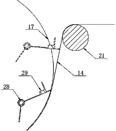
The invention provides a drum-type filtering device. The drum-type filtering device comprises a drum wheel, a filter belt, a driving roller device, a back-flushing device, a soiling solution return pipe, a detection switch, a scraping device, a residue filter tank, a purified liquid tank, a brushing roll and a device main body, wherein a soiling solution flows into a cavity of the drum wheel through the soiling solution return pipe, liquid is filtered by virtue of the filter belt and flows into the purified liquid tank for being machined by a machine tool, impurities in the soiling solution are blocked by the filter belt and are continuously settled to form a filter cake, after the filter cake is accumulated to a certain thickness on the surface of the filter belt, the filter belt rotatesalong with the driving roller device, and the filter belt with the surface attached with the filter cake part rotates outwards, so that the cycle use of the filter belt is realized; meanwhile, the device is further provided with the scraping device, a drying device and the like, so that the filter cake can be removed and dried; and the device has the advantages of good filtering performance, reliability in operation, simple and compact structure, low maintenance cost and the like, and the cycling filtration can be realized.

Description

technical field [0001] The invention belongs to the field of machine tool processing, in particular to the precise filtration of cutting fluid in the field of machine tool processing, and in particular to a drum filter device. Background technique [0002] In the case of high-precision machine tools or high precision parts machining, the cleanliness of the cutting fluid used is also required to be high, so it is necessary to carry out precise filtration of the cutting fluid. A filter and paper tape filter equipment, the filter is usually composed of a cylinder, a stainless steel filter, a sewage part, a transmission device and an electrical control part. After the liquid to be treated passes through the filter cartridge of the filter screen, its impurities are blocked. When cleaning is required, the detachable filter cartridge needs to be taken out and reinstalled after treatment. However, the filter has problems such as low filtration capacity, regular cleaning and replacem...

Claims


Application Information

Patent Timeline
Patent Type & Authority Applications(China)
IPC IPC(8): B01D33/41B01D33/067B01D33/11B01D33/056B01D33/04B01D33/46B01D33/50B01D33/70B01D33/76B01D33/66B01D33/80
CPCB01D33/04B01D33/056B01D33/067B01D33/11B01D33/41B01D33/461B01D33/466B01D33/50B01D33/66B01D33/705B01D33/76B01D33/80
Inventor 何国峰马同堂何立军赵敬
Owner 共享机床辅机(大连)有限公司
Learn More