Progressive die

A technology of progressive die and die base, applied in the field of progressive die, can solve the problems of inability to meet the requirements of manufacturing products, lower yield and work efficiency, inability to realize blanking work, etc., to meet product manufacturing requirements and reduce transportation. and warehouse occupancy, the effect of easy automated production

Active Publication Date: 2018-03-09
NINGBO ZHENYU TECH
View PDF6 Cites 3 Cited by
  • Summary
  • Abstract
  • Description
  • Claims
  • Application Information

AI Technical Summary

Problems solved by technology

[0002]In the prior art, the composite blanking die added on the progressive die generally has a structure of upper die, lower die, and a punch It is composed of a die, so that it is impossible to realize the punching work when it is necessary to punch more complex and large-volume products. Therefore, it is generally used to punch the holes in one-step mold, and then transfer it to another mold. Punching and blanking, such working methods lead to low manufacturing accuracy of the product, and large errors are prone to occur when re-aligning the benchmark, which greatly reduces the yield and work efficiency, so it cannot meet the requirements of manufacturing products

Method used


Image

  • Progressive die

Examples


Embodiment 1

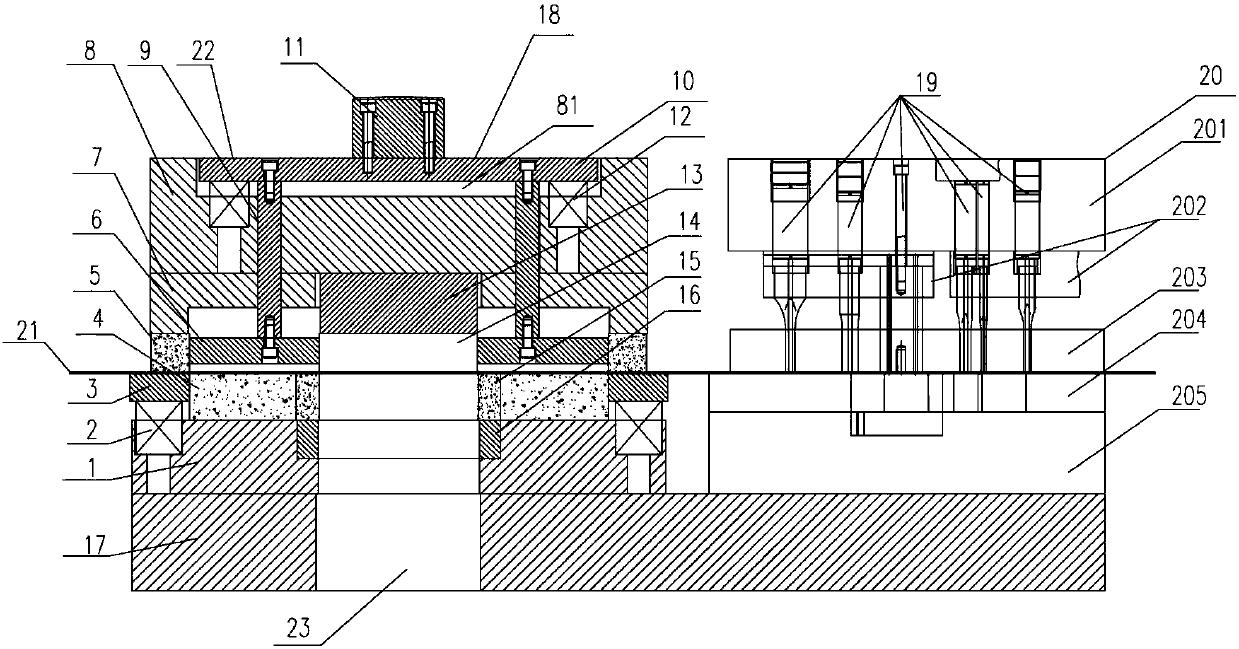
[0017] Such as figure 1 As shown, a progressive die described in this embodiment includes a lower die backing plate 17, and the lower die backing plate 17 is sequentially fixed with porous punching dies 20 for sequentially punching porous products, And the compound blanking die 22 that is used for punching, blanking, the compound blanking die 22 comprises upper mold base 8, blanking die fixed plate 7, blanking die 5, unloading plate 3 and The lower mold base 1 fixed with the lower mold base backing plate 17, the top of the upper mold base 8 is provided with a groove 81, the groove 81 has a push plate 10, and the bottom surface of the push plate 10 is fixed with a dowel 9; The concave part of the mold fixing plate 7 is matched with the through hole of the blanking die 5 to form a cavity, and the punching plate 6 is built in the cavity; After the plate 7 is fixed with the beating plate 6; the bottom surface of the upper die base 8 is fixed with an inner hole punch fixing plate ...


PUM

PropertyMeasurementUnit
lengthaaaaaaaaaa
lengthaaaaaaaaaa

Abstract

The invention discloses a progressive die. A porous punching dire and a compound punching die are fixed on a lower die seat base plate, wherein a concave groove is formed in the top of an upper die seat of the compound punching die; a push plate is arranged in the concave groove; a force transmission rod is fixed on the bottom surface of the push plate; a concave part of a blanking concave die fixing plate is correspondingly matched with a through hole of a blanking concave die to form a die cavity; a beating plate is arranged in the die cavity; the bottom of the force transmission rod is fixed with the beating plate; an inner hole convex die fixing plate is fixed on the bottom surface of the upper die seat; an inner hole convex die is arranged in a die hole of the beating plate; after theinner hole convex die penetrates through the blanking concave die fixing plate, the inner hole convex die is fixed with the inner hole convex die; an unloading plate is internally provided with a blanking convex die; an inner hole concave die is formed in the blanking convex die; a die hole of the inner hole concave die is correspondingly matched with the inner hole convex die and a die hole of alower die seat; a discharging hole is formed in the lower die seat base plate; a spring I is arranged between the unloading plate and the lower die seat. According to the structure of the progressivedie, punching work can be finished through work of a pair of dies on a punching machine; the rate of finished products and the working efficiency are improved and the manufacturing requirements of the products are met.

Description

technical field [0001] The invention relates to the structural technical field of a stamping die, in particular to a progressive die. Background technique [0002] In the prior art, the composite blanking die added to the progressive die generally has a structure consisting of an upper die, a lower die, a punch and a die, so that when punching is required, it is relatively complicated and bulky. Larger products cannot be punched, so it is generally used to punch the holes in one step of the mold, and then transfer to another mold for punching and blanking. This working method leads to the manufacturing accuracy of the product It is relatively low, and it is easy to generate large errors when re-aligning the reference, which greatly reduces the yield and work efficiency, so it cannot meet the requirements of manufacturing products. [0003] Therefore, the blanking process of adding a composite die to the progressive die is adopted to shorten the die length and meet the custo...

Claims


Application Information

Patent Timeline
Patent Type & Authority Applications(China)
IPC IPC(8): B21D37/08B21D28/14B21D28/34
CPCB21D28/14B21D28/34B21D37/08
Inventor 杨翔肖蒋宁邓晓根
Owner NINGBO ZHENYU TECH
Why Eureka
Try Eureka