Polygonal cutting blade with bulge parts in hole and cutter

A technology of cutting inserts and protrusions, applied in cutting inserts, tools for lathes, turning equipment, etc., can solve the problems of chipping cutting life, low cutting efficiency, deformation of fasteners, etc. of cutting inserts, so as to avoid cutting Vibration, improved cutting accuracy, and improved clamping rigidity

Active Publication Date: 2018-03-09
ZHUZHOU CEMENTED CARBIDE CUTTING TOOLS CO LTD
View PDF6 Cites 5 Cited by
  • Summary
  • Abstract
  • Description
  • Claims
  • Application Information

AI Technical Summary

Problems solved by technology

[0003] Although the cutting blade has the above advantages when it is clamped and cut through the center hole, the center axis of the fastener and the cutting blade are not concentric, and only a small area (or point) of contact with the center hole of the cutting blade can be produced when clamping, even if it is It can provide sufficient clamping force to the cutting blade, but the fastener is prone to multi-directional deformation during cutting, which induces cutting vibration, the cutting efficiency of the cutting blade is low during finishing machining, and the cutting blade is prone to chipping during high-efficiency cutting Short cutting life

Method used


Image

  • Polygonal cutting blade with bulge parts in hole and cutter
  • Polygonal cutting blade with bulge parts in hole and cutter
  • Polygonal cutting blade with bulge parts in hole and cutter

Examples


Embodiment 1

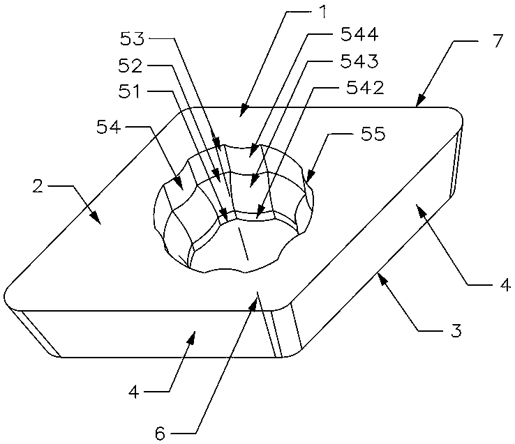
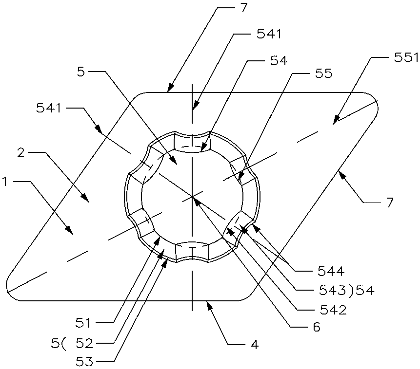
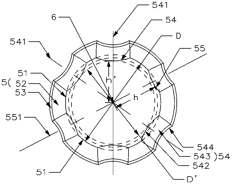
[0037] Such as Figure 1 to Figure 5 As shown, the polygonal cutting insert with protrusions in the hole of this embodiment includes a blade body 1 composed of an upper surface 2, a lower surface 3, and a plurality of side surfaces 4 connecting the upper surface 2 and the lower surface 3. The blade body 1 There is a central hole 5 that runs through the upper surface 2 and the lower surface 3. The blade body 1 is symmetrical about the central axis 6 of the central hole 5. Each side 4 intersects with the upper surface 2 to form a plurality of cutting edges 7. The inner surface of the central hole 5 corresponds to Each side 4 is provided with a raised portion 54 , and the raised portion 54 faces the corresponding side 4 .

[0038] In this embodiment, the blade body 1 is a parallelogram-shaped blade body as an example. The blade body 1 is provided with two sets of positioning sides, the positioning sides are composed of two adjacent sides 4, one set is the sides 4 on both sides o...

Embodiment 2

[0048] Such as Figure 6 As shown, the cutting tool of this embodiment includes a cutter body 10 and a fastening screw 11, and the cutter body 10 is provided with a sipe 101, including the cutting blade in Embodiment 1, and the cutting blade is installed in the sipe 101, tightly The set screw 11 is located in the central hole 5 and presses the cutting insert into the sipe 101. The cutter body 10 is a square cutter bar, only offers a knife groove 101 on the cutter body 10, and the cutting blade cooperates with the positioning surface of the knife groove 101 through a group of positioning sides. It is installed in the knife groove 101 through another set of positioning sides. The number of fastening screws 11 in contact with the protrusions 54 is three to six in the central hole 5 .

[0049] In this embodiment, the fastening screw 11 forms discontinuous contact with two adjacent protrusions 54 (the protrusions 54 on both sides of an acute angle) in the central hole 5, and the ...

Embodiment 3

[0053] Such as Figures 7 to 10 As shown, this embodiment is roughly the same as Embodiment 1, the only difference being:

[0054] In this embodiment, the blade body 1 is in the shape of a square plate, and four corner protrusions 55 are arranged to face the four right angles of the blade body 1 respectively. Group positioning sideways. With the change of the cutting force, an eight-fold constraint overclamping positioning can be formed in the center hole 5 of the insert body 1, and the principle is the same as that of the first embodiment.

[0055] In this embodiment, the blade body 1 has a horizontal middle section 9, the blade body 1 is symmetrical about the horizontal middle section 9, the inner surface of the center hole 5 above the horizontal middle section 9 and the inner surface of the center hole 5 below the horizontal middle section 9 are both A raised portion 54 is provided. Four cutting edges 7 are also formed between the lower surface 3 and the side surface 4, ...


PUM


Abstract

The invention discloses a polygonal cutting blade with bulge parts in a hole and a cutter. The polygonal cutting blade comprises a blade body consisting of an upper surface, a lower surface and a plurality of side surfaces connected with the upper surface and the lower surface, wherein a center hole penetrating through the upper surface and the lower surface is formed in the blade body, the bladebody is in central symmetry about the central axis of the center hole, each side surface and the upper surface intersect to form a plurality of cutting edges, one bulge part is arranged in the position, corresponding to each side surface, of the inner surface of the center hole, and the bulge parts directly face the corresponding side surfaces. The cutting blade has the characteristics of positioning reliability and stability, multiple clamping and long service life. The cutter comprises the cutting blade, fastening screws and the center hole of the cutting blade produce over-positioning multidirectional clamping under multiple constraints, deformation directions and areas unfavorable for fasteners are effectively controlled, the vibration of the cutting blade can be effectively attenuated during cutting, and the service life of the cutter is prolonged.

Description

technical field [0001] The invention relates to cutting processing technology, in particular to a polygonal cutting blade and a cutting tool with a protruding part in a hole. Background technique [0002] During the cutting process of the blade, the clamping strength and rigidity of the cutting blade have a great influence on the cutting ability of the cutting blade, and the clamping stability of the cutting slice especially has a substantial impact on the cutting efficiency and cutting accuracy of the cutting blade. The cutting blade with stable clamping not only has high cutting efficiency and precision but also has a long life. The cutting blade with unstable clamping is easy to generate vibration during cutting, which will cause the cutting blade to wear quickly or even break down, which greatly shortens the life of the cutting blade. . In order to improve the cutting performance of cutting inserts in the industry, cutting inserts are designed into a variety of cutting ...

Claims


Application Information

Patent Timeline
Patent Type & Authority Applications(China)
IPC IPC(8): B23B27/00B23B27/16
CPCB23B27/00B23B27/16B23B27/1625B23B2205/04
Inventor 王社权江爱胜刘敏
Owner ZHUZHOU CEMENTED CARBIDE CUTTING TOOLS CO LTD
Why Eureka
Try Eureka