Automatic cleaning device of machine tool worktable

An automatic cleaning and workbench technology, applied in the direction of manufacturing tools, metal processing equipment, metal processing machinery parts, etc., can solve the problems of high labor intensity, slow cleaning speed, narrow slides, etc., to reduce labor intensity and clear speed. , the effect of beneficial to safety

Inactive Publication Date: 2018-03-09
朱丽辉
View PDF0 Cites 4 Cited by
  • Summary
  • Abstract
  • Description
  • Claims
  • Application Information

AI Technical Summary

Problems solved by technology

[0002] The existing machine tool workbenches are provided with chute to facilitate the installation of bolts. However, due to the existence of chute, during the processing process, iron filings and other sundries often fall into the chute. The road is narrow and difficult to clean
Usually, the staff use manual work to clean up the sundries with brushes, the cleaning speed is slow, the efficiency is low, and the labor intensity is high.

Method used


Image

  • Automatic cleaning device of machine tool worktable

Examples


Embodiment Construction

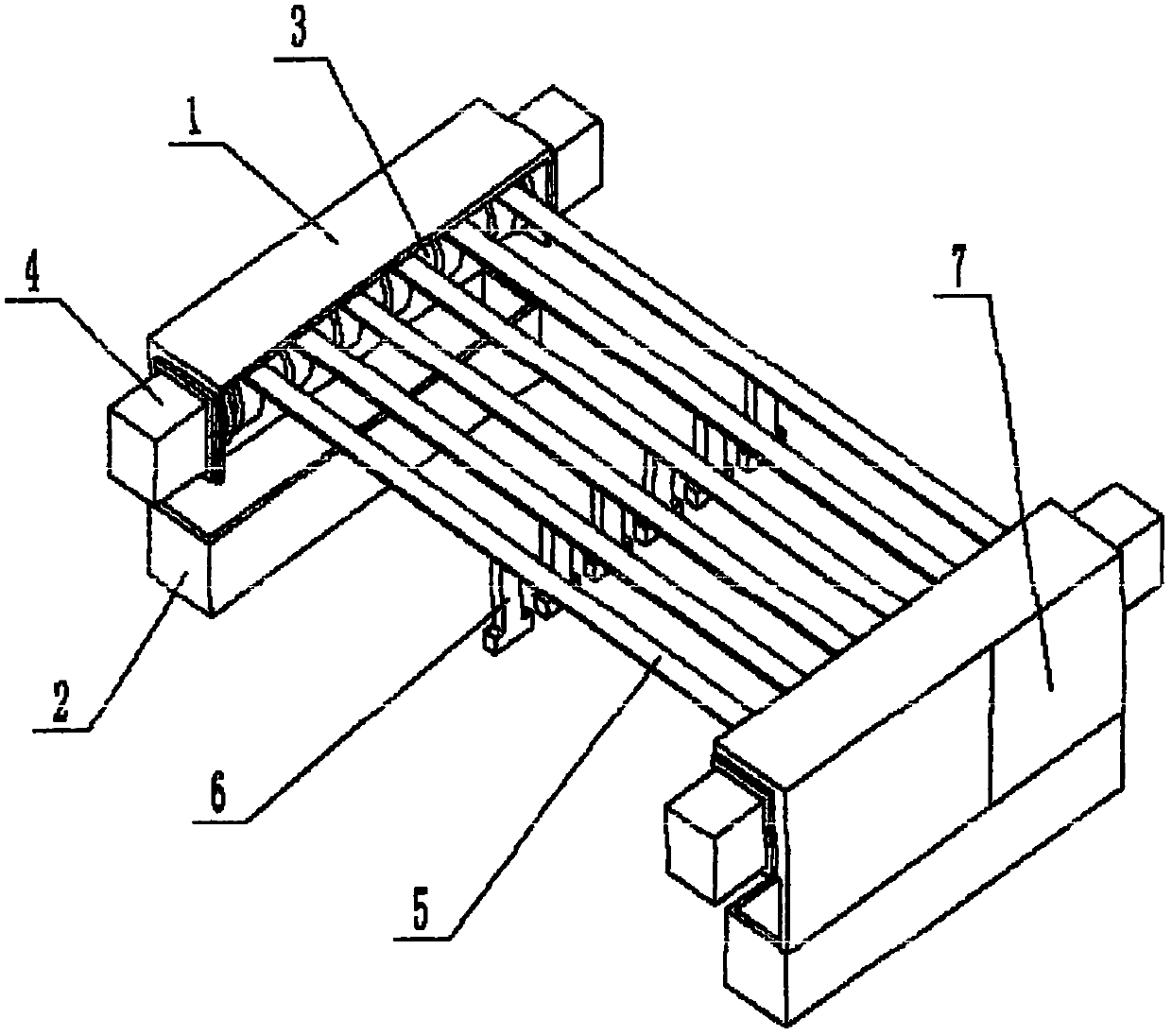
[0007] Referring to Figure 1, it includes a mounting frame 1, an iron scrap collection tank 2, a winding roller 3, a motor 4, a transmission belt 5, a brush head 6 and an operation panel 7, and the T-shaped brush head is clamped in the chute of the machine tool console, The iron filings collection tank 2 is fixedly connected to the bottom end of the mounting frame 1, the two ends of the rotating shaft of the winding roller 3 are flexibly connected to the mounting frame 1, and the end of the rotating shaft of the winding roller 3 is connected to the output shaft of the motor 4, and the motor 4 is installed At the front and back ends of the mounting frame 1; there are two mounting frame 1, iron scrap collection tank 2 and two winding rollers 3, the brush head 6 is connected to the lower surface of the transmission belt 5, and the two ends of the transmission belt 5 are wound on two winding rollers 3; the operation panel 7 is set on the outer wall of the installation frame 1. The...


PUM


Abstract

The invention relates to an automatic cleaning device for a machine tool workbench. It is mainly designed to solve the problem that the chute of the existing machine tool table is difficult to clean. It includes installation frame, iron chip collection tank, winding roller, motor, transmission belt, brush head and operation panel. The T-shaped brush head is clamped in the chute of the machine tool console, and the iron chip collection tank is fixedly connected to the bottom of the installation frame. The two ends of the rotating shaft of the winding roller are movably connected with the mounting frame, and the ends of the rotating shaft of the winding roller are connected with the output shaft of the motor, and the motor is installed at the front and rear ends of the mounting frame. There are two mounting frames, two iron scrap collecting tanks and two winding rollers, the brush head is connected to the lower surface of the transmission belt, and the two ends of the transmission belt are wound on the two winding rollers. The operation panel is arranged on the outer wall of the installation frame. The installation frame is connected with the chip collecting tank by screws, and the chip collecting tank is located under the winding roller. The advantage is that the removal speed is fast and the efficiency is high.

Description

technical field [0001] The invention relates to an automatic cleaning device for a machine tool workbench. Background technique [0002] The existing machine tool tables are equipped with chute to facilitate the installation of bolts. However, due to the existence of the chute, during the processing process, the processed iron filings and other sundries often fall into the chute. The road is narrow and difficult to clean. Usually all is that the staff adopts the mode of manual work to clean up sundry with brush, and cleaning speed is slow and efficient, and labor intensity is big. Contents of the invention [0003] The technical problem to be solved by the present invention is to provide an automatic cleaning device for the workbench of a machine tool, which can automatically remove the sundries inside the chute of the workbench, with fast removal speed and high efficiency, and reduced labor intensity. [0004] The above-mentioned purpose is achieved in this way: it incl...

Claims


Application Information

Patent Timeline
Patent Type & Authority Applications(China)
IPC IPC(8): B23Q11/00
CPCB23Q11/00B23Q11/0042
Inventor 朱丽辉
Owner 朱丽辉
Why Eureka
Try Eureka