Cutting traction equipment

A technology of equipment and cutting device, applied in metal processing equipment, clamping, supporting and other directions, can solve the problems of large volume, poor cutting accuracy and low efficiency of automatic cutting equipment, and achieve easy installation and later maintenance, convenient control, The effect of improving efficiency

Pending Publication Date: 2018-03-09
NEWTRY COMPOSITE
View PDF0 Cites 2 Cited by
  • Summary
  • Abstract
  • Description
  • Claims
  • Application Information

AI Technical Summary

Problems solved by technology

The commonly used cutting method is manual cutting. Manual cutting has many disadvantages, such as poor cutting accuracy, low efficiency, and frequent occurrence of safety accidents.
However, the automatic cutting equipment is large in size, too complicated in structure and expensive in cost.

Method used


Image

  • Cutting traction equipment
  • Cutting traction equipment
  • Cutting traction equipment

Examples


Embodiment 1

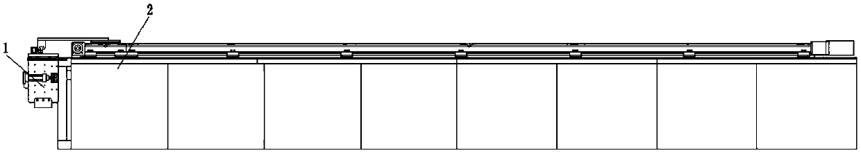
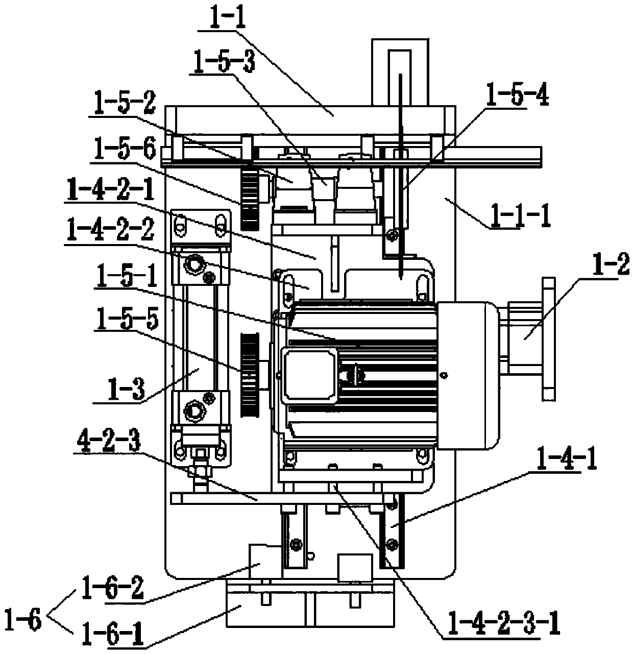
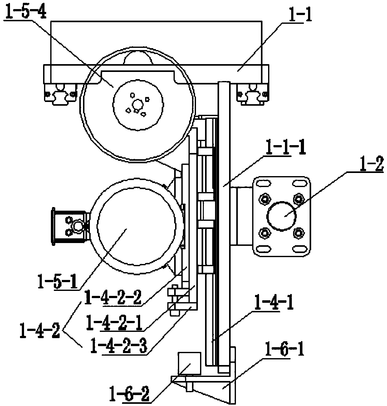
[0038] See Figure 1 to Figure 8 , the cutting and pulling device of this embodiment includes a cutting device 1 and a pulling device 2 .

[0039] The cutting device 1 includes a cutting table 1-1, a horizontal driving cylinder 1-2, a vertical driving cylinder 1-3, a sliding mechanism 1-4, a cutting mechanism 1-5 and a buffer mechanism 1-6. A mounting plate 1-1-1 extending downward is provided on the bottom surface of the cutting table 1-1. The laterally driven cylinder 1-2 drives the lateral displacement of the cutting table 1-1. The sliding mechanism 1-4 is located on the mounting plate 1-1-1. The cutting mechanism 1-5 is installed on the sliding mechanism 1-4. The vertical drive cylinder 1-3 drives the cutting mechanism 1-5 to move upwards along the sliding mechanism 1-4 and stretches out the top surface of the cutting table 1-1 to cut the material. The pulling device 2 pulls the material through the top surface of the cutting table 1-1.

[0040] The traction device 2 ...

Embodiment 2

[0054] See Figure 9 , This embodiment is basically the same as Embodiment 1, except that the linear module 2-2 includes a slide table 2-2-6, a screw rod 2-2-7 and a nut 2-2-8. Slide table 2-2-6 is fixed on the top surface of machine platform 2-1. The both sides of screw mandrel 2-2-7 are rotationally connected with the both sides of slide table 2-2-6, and the right side of screw mandrel 2-2-7 runs through the right side of slide table 2-2-6. The slide part 2-2-1 is slidingly connected with the slide rail of the slide table 2-2-6. The nut 2-2-8 is threadedly connected with the screw rod 2-2-7, and the bottom of the nut 2-2-8 is fixed with the sliding part 2-2-1. The output end of the worm gear reducer 2-4-2 of the traction drive mechanism 2-4 drives the screw mandrel 2-2-7 to rotate.


PUM


Abstract

The invention discloses cutting traction equipment. The cutting traction equipment comprises a cutting device and a traction device, wherein the cutting device comprises a cutting table plate, a transverse driving air cylinder, a vertical driving air cylinder, a sliding mechanism and a cutting mechanism; a mounting plate extending downwards is arranged on the bottom surface of the cutting table plate; the transverse driving air cylinder is used for driving the cutting table plate to transversely move; the sliding mechanism is arranged on the mounting plate; the cutting mechanism is mounted onthe sliding mechanism; the vertical driving air cylinder is used for driving the cutting mechanism to move upwards along the sliding mechanism and stretch out of a top surface cutting material of thecutting table plate; and the traction device is used for dragging a material to pass through the top surface of the cutting table plate. The cutting traction equipment is artful in structure; by utilizing a continuous cutting manner, the efficiency is increased, and stable and precise cutting is realized; and by virtue of the cooperation of the cutting device and the traction device, full-automatic cutting is realized, the manual cutting cost is greatly saved, and the control is convenient.

Description

technical field [0001] The invention relates to a cutting and pulling device. Background technique [0002] Before processing some tube-shaped, strip-shaped processing materials, it usually needs to be cut into the required length before subsequent processing. The commonly used cutting method is manual cutting. Manual cutting has many disadvantages, such as poor cutting accuracy, low efficiency, and frequent safety accidents. However, the automatic cutting equipment has a large volume, an overly complicated structure, and is expensive. Therefore, it is necessary to design a cutting and pulling device with low cost and high efficiency. Contents of the invention [0003] The purpose of the present invention is to provide a cutting and pulling device with low cost and high efficiency. [0004] The technical solution for realizing the purpose of the present invention is: a cutting and pulling device, including a cutting device and a pulling device; the cutting device includ...

Claims


Application Information

Patent Timeline
IPC IPC(8): B26D1/15B26D7/06B26D7/02B23Q7/00B23Q3/08
CPCB23Q3/08B23Q7/00B26D1/15B26D7/02B26D7/0683B26D2007/013
Inventor 陈云谈源邓嘉康包明华张俭范春雷
Owner NEWTRY COMPOSITE
Why Eureka
Try Eureka