Novel feeding device

A feeding device and a new type of technology, applied in the field of conveyor equipment, can solve the problems of uncontrollable material input speed, affecting the efficiency of transmission, delaying production efficiency, etc., and achieve the effect of simple structure, easy management, and easy maintenance and repair

Inactive Publication Date: 2018-03-09
天津金泰盛世石化设备有限公司
View PDF0 Cites 4 Cited by
  • Summary
  • Abstract
  • Description
  • Claims
  • Application Information

AI Technical Summary

Problems solved by technology

[0002] In industrial and agricultural production, conveyors are one of the preferred equipment for long-distance transport of materials. Especially with the development of modern industry, manufacturers have higher and higher requirements for the transport efficiency of conveyors. The transported materials More and more, but in the process of transportation, when the material is fed, sometimes the material will accumulate in the storage hopper, which will affect the efficiency of the transmission, and the existing conveying and feeding device cannot control the speed of the material input, and the material input Too fast or too slow will affect the production order, and the traditional roller conveyor feeding device has a relatively complicated structure. When a failure occurs, maintenance is more troublesome and production efficiency is delayed.

Method used


Image

  • Novel feeding device

Examples


Embodiment Construction

[0011] The following will clearly and completely describe the technical solutions in the embodiments of the present invention with reference to the accompanying drawings in the embodiments of the present invention. Obviously, the described embodiments are only some, not all, embodiments of the present invention. Based on the embodiments of the present invention, all other embodiments obtained by persons of ordinary skill in the art without making creative efforts belong to the protection scope of the present invention.

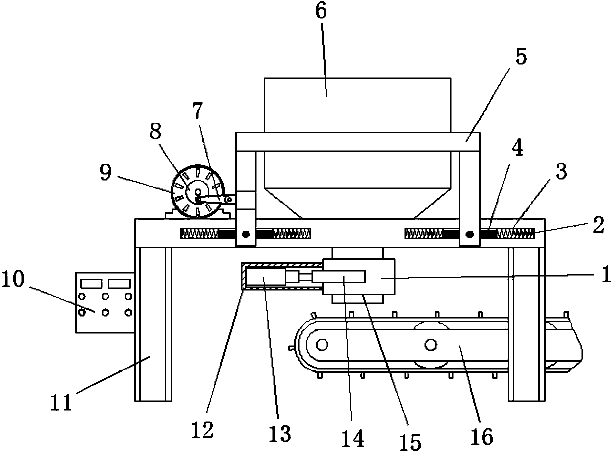
[0012] see figure 1 , the present invention provides a technical solution: a new feeding device, including a frame 11, a control device 10 is fixedly installed on the left side of the frame 11, and a slideway 3 is arranged on the upper part of the frame 11, and the The inner chamber middle part of slideway 3 is provided with slide block 4, and the both sides of described slide block 4 is provided with spring 2, and described spring 2 is fixedly connected with ...


PUM


Abstract

The invention discloses a novel feeding device, comprising a frame, a control device is fixedly installed on the left side of the frame, a slideway is arranged on the upper part of the frame, and a slide block is arranged in the middle of the inner cavity of the slideway , the two sides of the slider are provided with springs, the middle part of the slider is movably connected with a bracket through a hinge, the left side of the bracket is movably connected with a connecting rod through a hinge, and the left end of the connecting rod is movably connected with a hinge through a hinge. The runner, the rear side of the runner is fixedly connected with a motor, the upper part of the bracket is fixedly connected with a storage hopper, the lower part of the storage hopper is fixedly installed with a valve body, and the left side of the valve body is fixedly installed with a shell, An electric push rod is fixedly installed in the inner cavity of the housing, and a baffle is fixedly connected to the right end of the electric push rod. The invention is simple in structure, convenient and practical, easy to operate, easy to operate in later maintenance and repair, has uniform material transmission, high control precision, and can effectively ensure production efficiency.

Description

technical field [0001] The invention relates to the technical field of conveyor equipment, in particular to a novel feeding device. Background technique [0002] In industrial and agricultural production, conveyors are one of the preferred equipment for long-distance transport of materials. Especially with the development of modern industry, manufacturers have higher and higher requirements for the transport efficiency of conveyors. The transported materials More and more, but in the process of transportation, when the material is fed, sometimes the material will accumulate in the storage hopper, which will affect the efficiency of the transmission, and the existing conveying and feeding device cannot control the speed of the material input, and the material input Too fast or too slow will affect the production order, and the traditional roller conveyor feeding device has a relatively complicated structure. When a failure occurs, maintenance is more troublesome and delays pr...

Claims


Application Information

Patent Timeline
Patent Type & Authority Applications(China)
IPC IPC(8): B65G47/19
CPCB65G47/19
Inventor 赵德立
Owner 天津金泰盛世石化设备有限公司
Why Eureka
Try Eureka