
A kind of viaduct pier beam and its construction technology

A technology for viaduct piers and beams, which is applied in the field of preparation process of viaduct pier beams, which can solve the problems of long-term road closures, numerous procedures, and long construction periods, and achieve long construction periods, increased bending and compression resistance, and smooth construction. short cycle effect

Active Publication Date: 2020-01-17
永嘉县信达智能设备制造有限公司
View PDF6 Cites 0 Cited by
  • Summary
  • Abstract
  • Description
  • Claims
  • Application Information

AI Technical Summary

Problems solved by technology

[0003] For the construction of traditional viaduct piers, it is necessary to drill holes in the ground before pouring the steel bars and concrete, and the prefabricated slabs must be set up on the ground for watering, so that due to the many procedures and long construction period during construction, it is more necessary to construct on the original road. Road closed for a long time

Method used


Image

  • A kind of viaduct pier beam and its construction technology
  • A kind of viaduct pier beam and its construction technology
  • A kind of viaduct pier beam and its construction technology

Examples


Embodiment 1

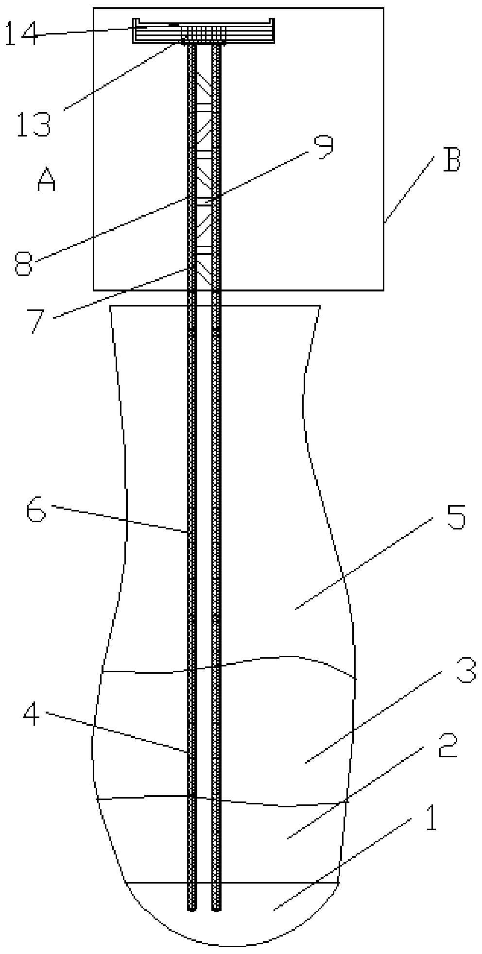
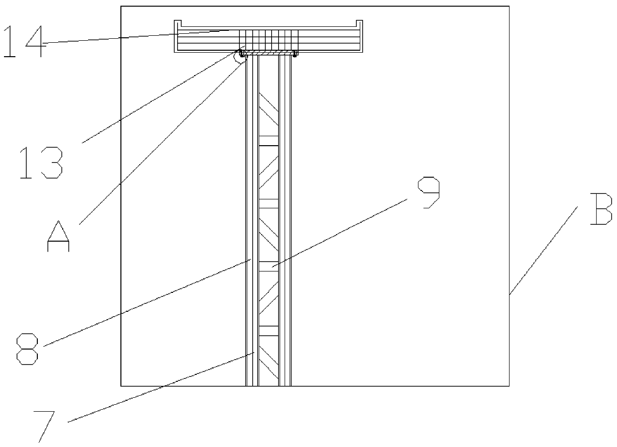
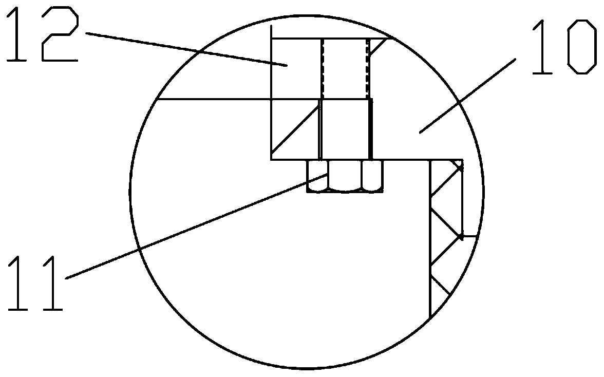
[0033] Embodiment 1:, a bridge pier crossbeam of viaduct, comprises crossbeam 14 and several pier piers, is characterized in that: said pier is made up of a terminal pipe 4, several middle-end pipes 6 and a top pipe 7, and said end The pipe 4, the middle pipe 6 and the top pipe 7 are injected with micro-expanded concrete 8, the middle part of the beam 14 is provided with a threaded steel cage 13, the top of the pier is provided with a pier connecting steel plate 10, and the bottom of the crossbeam 14 is provided with The crossbeam connecting steel plate 12 is fixed by connecting screws 11 between the crossbeam connecting steel plate 12 and the pier connecting steel plate 10, and the end pipe 4, the middle end pipe 6 and the top pipe 7 are all thick-walled steel pipes, and are connected by threads. The surface of the bridge pier adopts anti-corrosion treatment or anti-corrosion material, the surface of the pier connecting steel plate 10 and the beam connecting steel plate 12 ado...

Embodiment 2

[0035] An elevated bridge pier crossbeam, comprising a crossbeam 14 and several piers, is characterized in that: the pier is composed of a terminal pipe 4, several middle-end pipes 6 and a top pipe 7, the end pipe 4, the middle pipe Micro-expanded concrete 8 is injected into the pipe 6 and the top pipe 7, a threaded steel cage 13 is arranged in the middle of the crossbeam 14, a pier connecting steel plate 10 is arranged on the top of the pier, and a crossbeam connecting steel plate 12 is arranged on the bottom of the crossbeam 14, The beam connecting steel plate 12 and the bridge pier connecting steel plate 10 are fixed by connecting screws 11, the surface of the bridge pier adopts anti-corrosion treatment or adopts corrosion-resistant materials, and the end pipe 4, the middle end pipe (6) and the top end pipe 7 are all Thick-walled steel pipes are welded to each other. The bottom of the end pipe 4 is pointed or convex. The surface of the connecting steel plate 10 for the pier ...


PUM


Abstract

The invention discloses an elevated bridge pier beam and a construction technology thereof and aims at solving the problems that steel bars and concrete are poured after the ground is needed to be drilled, and a prefabricated slab is built at the aboveground part to perform pouring, so that construction on an original road more needs road closure for a long time as various procedures and long construction period during construction of the traditional elevated bridge pier construction. The elevated bridge pier beam is simple in structure; micro-expansion concrete is poured in a tail end pipe, amiddle end pipe and a top end pipe, so that improvement on the flexural performance and the compressive performance of the pipes is facilitated; and the internally poured concrete can have micro expansion, cannot have shrinkage holes or cracks after being thoroughly solidified and forms a certain pre-expansion force inside. A bridge pier is formed by welding or threaded connection of the three ofthe tail end pipe, the middle end pipe and the top end pipe; and as thick wall steel pipes are adopted, rapid piling can be realized, the construction period is short, the occupying place is small, and building of the prefabricated slab is not needed.

Description

technical field [0001] The invention relates to the technical field of viaduct structures, in particular to a preparation process for viaduct pier beams. Background technique [0002] With the development of society, the convenience of transportation has become a major aspect that various countries pay attention to. Viaducts are also products that cater to the development of this era. Viaducts, that is, overpass bridges, are a kind of bridge. A bridge spanning valleys, rivers, roads, or other low obstacles, especially with high-supported towers or pillars resting on a series of narrow reinforced concrete or masonry arches. After the city develops, the traffic is congested, the buildings are dense, and the streets are difficult to widen. Using this kind of bridge can evacuate the traffic density and improve the transportation efficiency. In addition, in highways or railways between cities, in order to avoid crossing with other lines, save land, and reduce subsidence of the r...

Claims


Application Information

Patent Timeline
Patent Type & Authority Patents(China)
IPC IPC(8): E01D21/00E01D19/02
CPCE01D19/02E01D21/00
Inventor 金勇
Owner 永嘉县信达智能设备制造有限公司
Learn More