
Laser scanning device, image forming apparatus and reflection surface identification method

A technology of an optical scanning device and an identification method, which is applied to an electrical recording process applying a charge pattern, an equipment of an electrical recording process applying a charge pattern, optics, etc., can solve problems such as shortening the life of a memory, and achieve the effect of reducing the number of updates.

Active Publication Date: 2018-03-09
KYOCERA DOCUMENT SOLUTIONS INC
View PDF3 Cites 2 Cited by
  • Summary
  • Abstract
  • Description
  • Claims
  • Application Information

AI Technical Summary

Problems solved by technology

Therefore, the lifetime of the memory of the image forming apparatus is shortened

Method used


Image

  • Laser scanning device, image forming apparatus and reflection surface identification method
  • Laser scanning device, image forming apparatus and reflection surface identification method
  • Laser scanning device, image forming apparatus and reflection surface identification method

Examples


Embodiment Construction

[0018] Embodiments of the present invention will be described below with reference to the accompanying drawings for easy understanding of the present invention. In addition, the following embodiment is only an example which actualized this invention, and does not limit the technical scope of this invention.

[0019] [Schematic Configuration of Image Forming Apparatus 10 ]

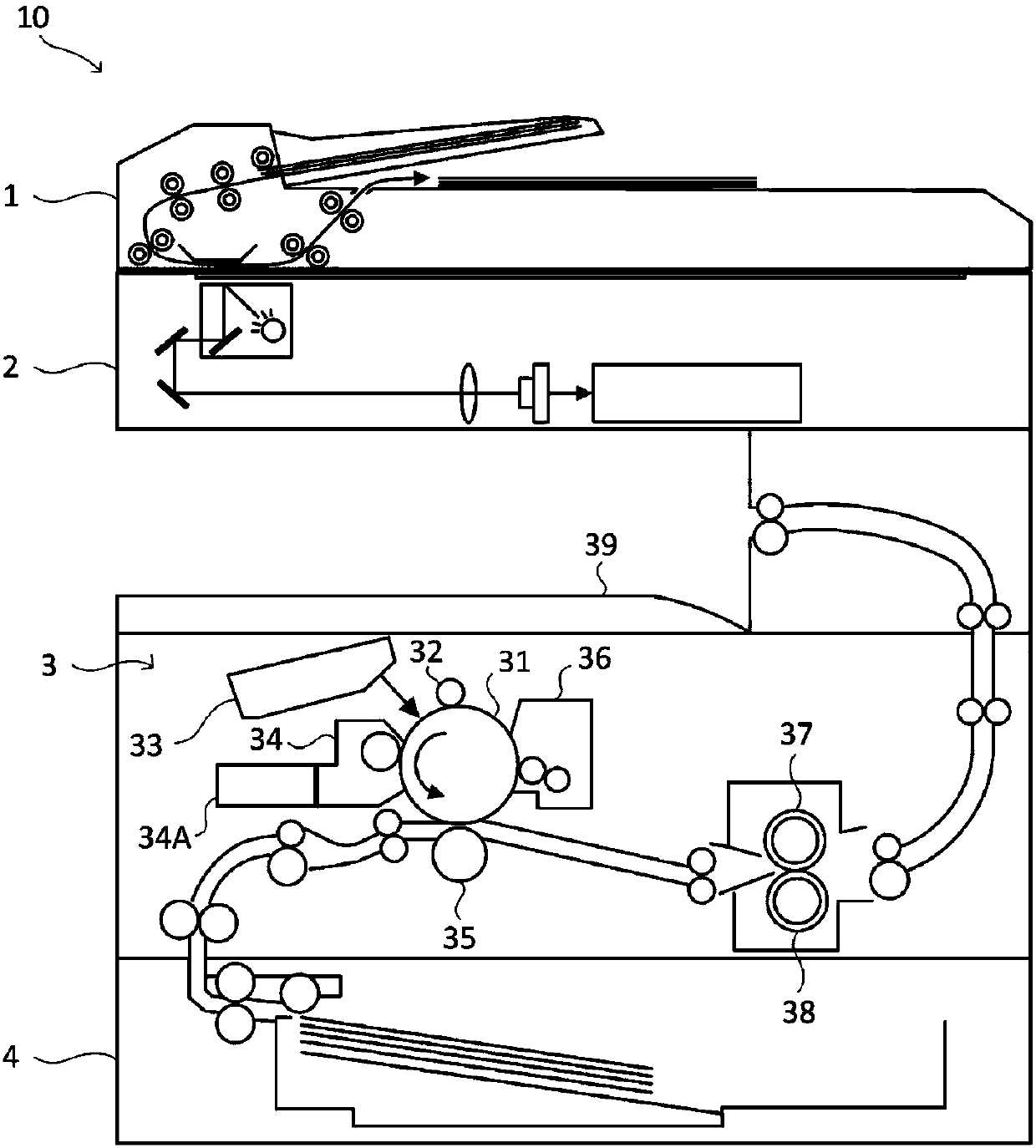
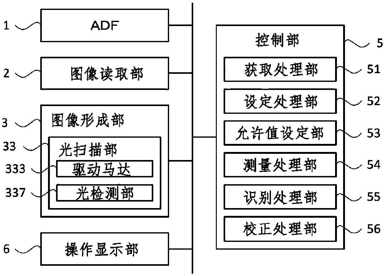
[0020] First, refer to figure 1 and figure 2 , the schematic configuration of the image forming apparatus 10 according to the embodiment of the present invention will be described. in, figure 1 is a schematic cross-sectional view showing the configuration of the image forming apparatus 10 .

[0021] The image forming apparatus 10 is a digital multifunction peripheral having a scanning function for reading image data from a document, a printing function for forming an image based on the image data, and multiple functions such as a facsimile function and a copy function. In addition, the present inventi...


PUM


Abstract

The invention discloses a laser scanning device which can reduce the number of updates of the memory, and identify a reflection surface of the polygon mirror while allowing the shift of the detectioninterval that is generated due to environmental variations. The laser scanning device includes a rotary polygon mirror, a drive motor, a light detecting portion, a measurement processing portion, andan identification processing portion. The rotary polygon mirror has reflection surfaces and rotates such that light is scanned by the reflection surfaces in sequence. The light detecting portion detects the light scanned by the rotary polygon mirror. The measurement processing portion, in each of light detection cycles, measures an interval between a light detection timing and an output timing atwhich a drive signal that is to be input to a drive motor first after the detection timing, is output. The identification processing portion identifies a reflection surface corresponding to a standardinterval, based on the standard interval and the measured interval, the standard interval being one of intervals acquired in the detection cycles that correspond to the reflection surfaces.

Description

technical field [0001] The present invention relates to an optical scanning device equipped with a rotating polygon mirror, an image forming device equipped with the optical scanning device, and a reflection surface recognition method executed in the optical scanning device. Background technique [0002] In an image forming apparatus such as a printer capable of forming images by electrophotography, light emitted from a light source according to image data is scanned on a photosensitive drum by a rotating polygon mirror to form an electrostatic latent image corresponding to the image data on the photosensitive drum. In such an image forming apparatus, the timing of emitting light corresponding to each line of image data, that is, the writing of an electrostatic latent image, is determined based on the timing of detection of light in a light detection unit capable of detecting light from a light source scanned by a rotating polygon mirror. opportunity. [0003] Also, a struc...

Claims


Application Information

Patent Timeline
IPC IPC(8): G02B26/12G03G15/04G03G15/00
CPCG02B26/12G03G15/0409G03G15/50G02B26/127G02B26/121G03G15/043
Inventor 中井润
Owner KYOCERA DOCUMENT SOLUTIONS INC
Learn More