
Method for determining anisotropy coefficient of resistivity of reservoir

An anisotropic and deterministic technology, applied in the fields of electrical digital data processing, earthwork drilling and production, complex mathematical operations, etc., can solve the problem of high logging cost, inapplicability, and inability to obtain continuously changing anisotropy coefficients of reservoirs. The anisotropy coefficient of the core section can be quickly and accurately determined

Active Publication Date: 2018-03-09
BC P INC CHINA NAT PETROLEUM CORP +1
View PDF5 Cites 4 Cited by
  • Summary
  • Abstract
  • Description
  • Claims
  • Application Information

AI Technical Summary

Problems solved by technology

[0005] The above two technical methods have the following problems. The anisotropy coefficient of a certain depth point can only be obtained through the core test measurement, and the anisotropy coefficient of the continuous change of the reservoir and the anisotropy coefficient of the uncored section cannot be obtained. The method is limited; triaxial induction resistivity logging can accurately measure the continuously changing anisotropy coefficient, vertical resistivity and horizontal resistivity of the reservoir, but the logging cost of this method is high and cannot be applied in some old wells. Cannot make full use of the resistivity data measured in old wells to calculate the anisotropy coefficient

Method used


Image

  • Method for determining anisotropy coefficient of resistivity of reservoir
  • Method for determining anisotropy coefficient of resistivity of reservoir
  • Method for determining anisotropy coefficient of resistivity of reservoir

Examples


Embodiment Construction

[0029] The specific implementation of this embodiment will be described in further detail below to support the technical problem to be solved by the present invention, but it is not used as a basis for any limitation on the invention.

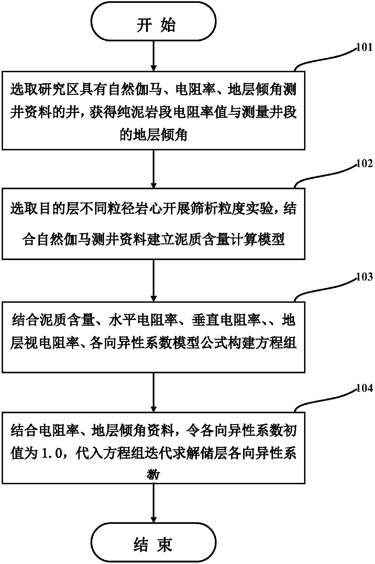
[0030] Such as figure 1 As shown, a method for interpreting a water-flooded layer in a horizontal well based on LWD provided by an embodiment of the present invention includes the following steps:

[0031] Step 101: Select the wells in the study area that have logging data of natural gamma ray, resistivity and formation dip angle, and obtain the resistivity value of the pure mudstone section and the formation dip angle of the measured well section;

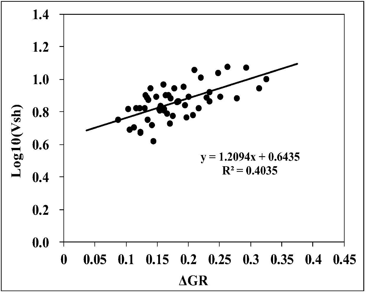
[0032] Step 102: Select cores of different particle sizes in the target layer to carry out sieving particle size experiments, and establish a calculation model for shale content in combination with natural gamma ray logging data;

[0033] Step 103: Combining shale content, horizontal resistivity, ...


PUM


Abstract

The invention discloses a method for determining the anisotropy coefficient of the resistivity of a reservoir. The method includes the following steps that a well with natural gamma, resistivity, anddip logging data in a study area is selected firstly, the resistivity value of a pure shale section and the stratum dip angle of a measured well section are obtained; rock cores, different in particlesize, of a target layer are selected for carrying out the granularity sieve-analysis experiment, and through the combination with the natural gamma well-log information, a mud content calculation mode is built; through the combination of the mud content, the horizontal resistivity, the vertical resistivity, the anisotropy coefficient and the apparent formation resistivity model formula, an equation set is formed; through the combination of the resistivity and the stratum dip angle, the initial value of the anisotropy coefficient is made to be 1.0 and is substituted into the equation set for obtaining the anisotropy coefficient of the reservoir through iterative solution. When the method is actual use, without the rock-core resistivity anisotropy coefficient experiment, by using the well-logging data and a theoretical model, the anisotropy coefficient of the resistivity of the reservoir is obtained through iterative solution, and a basic parameter is provided for accurate correction ofthe resistivity of the reservoir.

Description

technical field [0001] The invention belongs to the field of logging data correction of oil and gas reservoirs with complex structures in petroleum exploration, and relates to a method for determining the anisotropy coefficient of resistivity of reservoirs. Background technique [0002] At present, there are two methods to determine the anisotropy coefficient of reservoir resistivity, one is to obtain the anisotropy coefficient at a fixed depth point through core experiment measurement, and the other is to measure the anisotropy coefficient through triaxial induction resistivity logging tools Calculate the reservoir anisotropy coefficient. The core test method is to use the coring data of the target layer to carry out core sampling, measure the resistivity of the rock sample parallel to the bedding direction of the core, and measure the resistivity of the rock sample perpendicular to the bedding direction of the core. The following formula calculates the anisotropy coeffici...

Claims


Application Information

Patent Timeline
IPC IPC(8): G06F17/50G06F17/12E21B49/00
CPCE21B49/00G06F17/12G06F30/20
Inventor 王谦于华苏波李国利崔式涛虞兵袁龙廖茂杰姚亚彬段朝伟高衍武鲁明宇
Owner BC P INC CHINA NAT PETROLEUM CORP
Learn More