Lithium battery cap pressure welding device

A technology for lithium batteries and caps, which is applied to battery caps/end caps, resistance welding equipment, battery pack components, etc., can solve the problems affecting the pressure welding effect of lithium battery caps, poor sealing between caps and tube shells, and low safety performance. and other problems, to achieve the effect of good sealing performance, increase profit, and improve production efficiency

Inactive Publication Date: 2018-03-13
黄思珍
View PDF3 Cites 2 Cited by
  • Summary
  • Abstract
  • Description
  • Claims
  • Application Information

AI Technical Summary

Problems solved by technology

[0004] In view of the deficiencies in the prior art, the purpose of the present invention is to provide a lithium battery cap welding device to solve the problem that the general process is complicated and manual operation is required, and the vibration generated during the working process of the equipment will easily lead to poor sealing of the connection between the cap and the shell, thus affecting Lithium battery cap pressure welding effect, low safety performance and low production efficiency, high labor costs

Method used


Image

  • Lithium battery cap pressure welding device
  • Lithium battery cap pressure welding device
  • Lithium battery cap pressure welding device

Examples


Embodiment

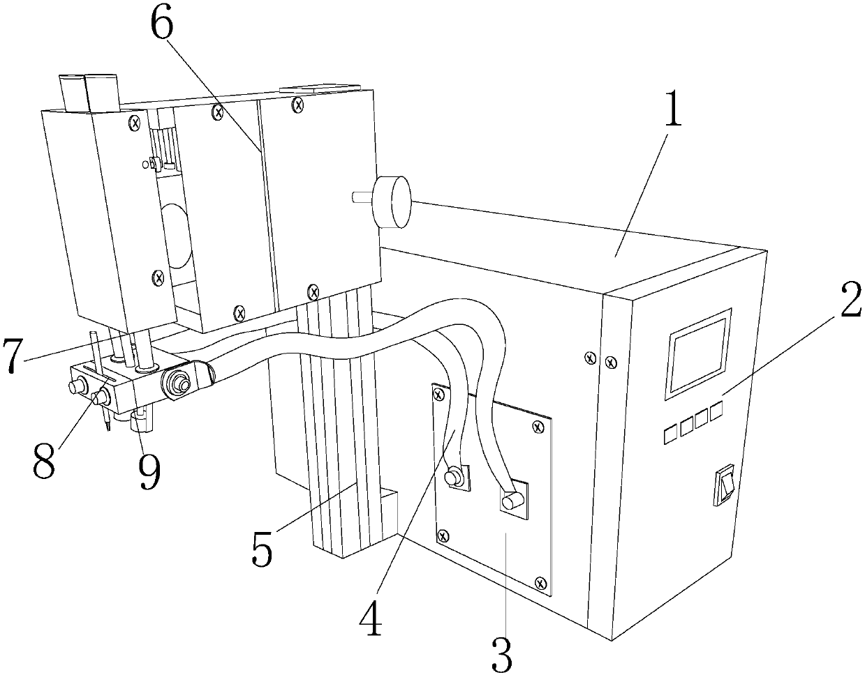
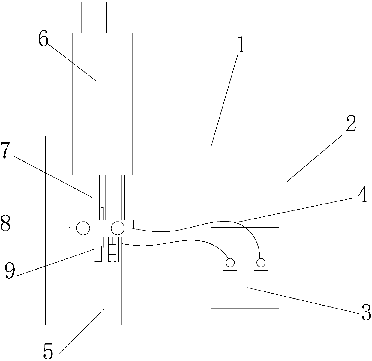
[0030] see Figure 1-Figure 7 , the invention provides a lithium battery cap pressure welding device: its structure includes a chassis 1, a control panel 2, a sealing connecting plate 3, a welding wire tube 4, a lifting rod 5, a welding control head 6, a telescopic rod 7, and a welding head 8 . The battery cap gland device 9, the chassis 1 is a cuboid, the front end is provided with a control panel 2, the rear of the control panel 2 is interlocked with the front of the chassis 1 and connected by nut locking, and the sealing connecting plate 3 is welded It is located at the lower right side of the left side of the chassis 1 and is electrically connected to the welding wire tube 4. One end of the welding wire tube 4 is respectively connected to the left and right sides of the welding head 8, and the other end is electrically connected to the chassis 1 through the sealing connecting plate 3. The lifting rod 5 is installed in the middle end of the left side of the chassis 1 and on...


PUM


Abstract

The invention discloses a lithium battery cap pressure welding device. The lithium battery cap pressure welding device structurally comprises a machine case, a control panel, a sealing connecting plate, welding wire pipes, a lifting rod, a welding control machine head, a telescopic rod, a welding head and a battery cap pressing and covering device. The machine case is a cuboid, the control panel is arranged at the front end of the machine case, and the rear portion of the control panel and the front portion of the machine case are buckled and connected through nuts in a locked manner. The sealing connecting plate is welded to the lower right position of the left side of the machine case and electrically connected with the welding wire pipes. One ends of the welding wire pipes are connectedto the left side and the right side of the welding head correspondingly, and the other ends of the welding wire pipes are electrically connected with the machine case through the sealing connecting plate. The lifting rod is arranged at the middle end of the left side of the machine case and arranged on the left side edge of the sealing connecting plate. The lithium battery cap pressure welding device has the beneficial effects that by means of the lithium battery cap pressure welding device, a vertical pressing device can be used for tightly pressing a cap and a pipe shell, the sealing performance is good, the safety quality is improved, manual operation is not needed, cost is reduced, the production efficiency of enterprises is improved, profits are increased, and convenience and practicability are achieved.

Description

technical field [0001] The invention relates to a lithium battery cap pressure welding device, which belongs to the field of battery cap pressure welding devices. Background technique [0002] A lithium battery is a primary battery that uses lithium metal or lithium alloy as the negative electrode material and uses a non-aqueous electrolyte solution. It is different from a rechargeable battery. Lithium-ion batteries are different from lithium-ion polymer batteries. The inventor of the lithium battery is Edison. Due to the very active chemical properties of lithium metal, the processing, storage and use of lithium metal have very high environmental requirements. Therefore, lithium batteries have not been used for a long time. With the development of microelectronics technology at the end of the 20th century, miniaturized equipment is increasing day by day, which puts forward high requirements for power supply. Lithium batteries have entered a large-scale practical stage. ...

Claims


Application Information

Patent Timeline
Patent Type & Authority Applications(China)
IPC IPC(8): B23K11/31B23K11/02H01M2/04H01M50/147
CPCB23K11/02B23K11/31H01M50/147Y02E60/10
Inventor 黄思珍
Owner 黄思珍
Why Eureka
Try Eureka