
Heat-resisting building sealing strip

A sealing strip and construction technology, which is applied in the direction of construction, building components, sealing devices, etc., can solve the problems of small grip force of fitting parts, water leakage and air leakage, and affect the sealing effect, so as to facilitate compression and sealing, ensure the sealing effect, and improve the grip force effect

Inactive Publication Date: 2017-11-28
钱振宇
View PDF0 Cites 0 Cited by
  • Summary
  • Abstract
  • Description
  • Claims
  • Application Information

AI Technical Summary

Problems solved by technology

From the perspective of sealing, it is a better treatment method, but this method also has the following four disadvantages: 1) The cost of prefabricated corners is high; 2) This only transfers the defective parts of the seal to not far from the corners, and prefabricated corners The physical connection with the sealing strip may still be a hidden danger of water and air leakage; 3) The joint between the prefabricated corner and the sealing head is unsightly; 4) If you encounter doors and windows with complex cross-sections, this treatment method is powerless; 5) Now Some sealing strips are made of pure rubber material, so they have little grip on the mating parts and poor flexibility during the bending operation, which cannot meet the needs of customers; 6) After the existing sealing strips are used for a long time, the surface will be oxidized , which affects the normal operation of the overall equipment and cannot meet the needs of customers
[0003] During the use of existing sealing strips, heat will be generated due to the influence of the environment and extrusion. If the heat resistance is not good, the sealing effect will be affected

Method used


Image

  • Heat-resisting building sealing strip
  • Heat-resisting building sealing strip

Examples


Embodiment Construction

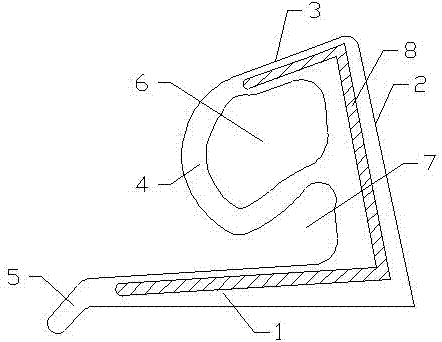
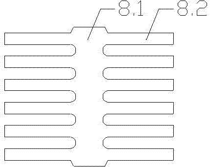
[0022] see Figure 1-2 , a heat-resistant building sealing strip in the present invention includes a transverse section 1, a first inclined section 2, a second inclined section 3 and an arc section 4, the outer side of the transverse section 1 is a straight edge, and the inner side is a hypotenuse, and the The outside of the first oblique section 2 is a straight edge, slanting to the upper left, and the inner side is a curved edge. The outer side of the second oblique section 3 is a straight edge, obliquely to the lower left, and the inner side is a curved edge. The horizontal section 1 and the first school section 2 and the second oblique section 3 are connected end to end, and the left end of the horizontal section 1 is provided with a foot 5, which is convenient for construction personnel to locate during installation. The arc section 4 is located on the inner side of the first oblique section 2, and the arc section 4 One end is connected with the left end of the second obl...


PUM


Abstract

The invention relates to a heat-resistant building sealing strip. It includes a horizontal section (1), a first oblique section (2), a second oblique section (3) and an arc section (4), the left end of the horizontal section (1) is provided with a foot (5), and the arc section (4 ) is located inside the first oblique section (2), and one end of the arc section (4) is connected to the left end of the second oblique section (3), and the other end is connected to the middle of the first oblique section (2), and the arc section (4 ), the first hypotenuse (2) and the second hypotenuse (3) form a hollow structure (4), the lower side of the arc (4), the first oblique section (2) and the horizontal section (1) form a bayonet ( 7), the sealing strip is embedded with a comb-shaped insert (8) made of resin, and the surface of the sealing strip is coated with a heat-resistant coating. The invention relates to a heat-resistant building sealing strip, which can effectively resist heat and has good sealing effect. At the same time, the sealing member has a large grasping force on matching parts and has good flexibility in the bending operation process.

Description

technical field [0001] The invention relates to a sealing strip, which is suitable for doors and windows with complex profile sections. The utility model belongs to the technical field of accessories for building doors, windows and curtain walls. Background technique [0002] During the use of building doors, windows and curtain walls after installation, the corners are the main parts of the doors, windows and curtain walls for water and air leakage. The treatment methods at the corners and corners are as follows: 1) The cut-off sealing strips are only physically lapped. Any other treatment; 2) Cold glue the sealing strip with quick-drying glue on site; 3) Install the factory-prefabricated corners. Among them, the first two are mainly used in some low-end door and window curtain walls, while the third type is often used in high-end door and window curtain walls. From the perspective of sealing, it is a better treatment method, but this method also has the following four di...

Claims


Application Information

Patent Timeline
IPC IPC(8): C09D161/14C09D163/00C09D131/04C09D7/12E04B1/686E06B7/23
CPCC09D161/14C08L2201/08C08L2205/035C09D5/18C09D131/04C09D163/00E04B1/6813E06B7/2314C08L63/00C08L31/04C08K13/02C08K2003/265C08K2003/2227C08K2003/387C08L61/14
Inventor 钱振宇
Owner 钱振宇
Learn More