Novel welding device

A welding device, a new type of technology, applied in auxiliary devices, welding equipment, auxiliary welding equipment, etc., can solve the problems of reduced service life, waste of power resources, short power supply lines, etc., to reduce impact, save electricity, and reduce waste Effect

Inactive Publication Date: 2018-03-13
广东龙城建筑工程有限公司
View PDF7 Cites 0 Cited by
  • Summary
  • Abstract
  • Description
  • Claims
  • Application Information

AI Technical Summary

Problems solved by technology

[0002] At present, electric welding machines are used more and more widely. However, due to the short power supply line setting of electric welding machines, it often affects the movement of electric welding machines during welding. In the past, when encountering similar phenomena, one or more terminal boards are generally used. Extend the connection to achieve the purpose of plugging and powering the electric welding machine. However, after connecting multiple terminal boards, the power supply wire has a certain length, which is extremely inconvenient when retracting, and the power supply wire is exposed to the outside for a long time when it is not in use. damaged, the service life is reduced; there are many welding machine power distribution devices that can automatically retract and unwind the wires, but they need to be powered by the mains to control the operation, resulting in a waste of power resources

Method used


Image

  • Novel welding device
  • Novel welding device
  • Novel welding device

Examples


Embodiment Construction

[0023] All features disclosed in this specification, or steps in all methods or processes disclosed, may be combined in any manner, except for mutually exclusive features and / or steps.

[0024] Any feature disclosed in this specification (including any appended claims, abstract and drawings), unless expressly stated otherwise, may be replaced by alternative features which are equivalent or serve a similar purpose. That is, unless expressly stated otherwise, each feature is one example only of a series of equivalent or similar features.

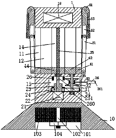
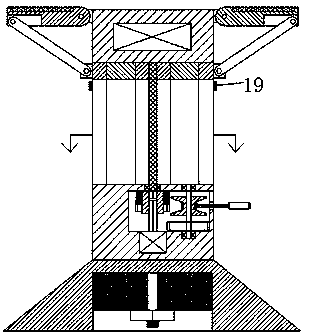
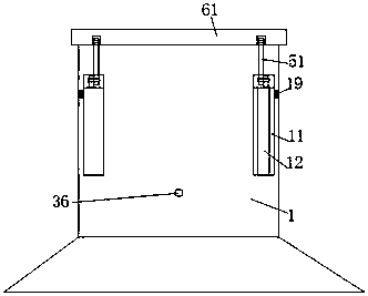
[0025] like Figure 1-5 As shown, a new type of welding device of the present invention includes a distribution box 1 and a light energy device, a support portion is provided under the distribution box 1, and an assembly cavity 15 is provided in the bottom of the distribution box 1. A motor 21 is fixedly installed in the bottom wall of the assembly chamber 15, and a rotating column 22 is fixedly arranged on the top of the motor 21, and a sepa...


PUM


Abstract

The invention discloses a novel welding device which comprises a distribution box and a luminous energy device. A supporting portion is arranged below the distribution box. An assembling cavity is formed in the bottom of the distribution box, a motor is fixedly installed in the bottom wall of the assembling cavity, a rotary column is fixedly arranged on the top of the motor, a separation barrel sleeve is installed on the rotary column in a sliding mode, a toothed wheel is fixedly installed on the separation barrel sleeve, a toothed disc engaged with the toothed wheel is installed in the assembling cavity through the rotary column, a reel is fixedly installed on the rotary column and provided with a cable, the cable penetrates through a penetrating hole formed in the side wall of the assembling cavity and is extended outwards, the tail end of the cable is fixedly provided with a power transmission base, a pull handle is fixedly arranged on the end face of the right side of the power transmission base, multiple sets of inserting holes are formed in the top of the power transmission base in the front-back direction, the luminous energy device comprises assembling plates and luminous plates, the assembling plates are rotationally installed at the upper ends of the two side walls of the distribution box in a left-right symmetrical mode, the luminous energy plates are fixedly installed in the assembling plates, and the distribution box is further internally provided with a power storage plate electrically connected with the luminous energy plates and the motor and a twisting portion.

Description

technical field [0001] The invention relates to the field of welding technology, in particular to a novel welding device. Background technique [0002] At present, electric welding machines are used more and more widely. However, due to the short power supply line setting of electric welding machines, it often affects the movement of electric welding machines during welding. In the past, when encountering similar phenomena, one or more terminal boards are generally used. Extend the connection to achieve the purpose of plugging and powering the electric welding machine. However, after connecting multiple terminal boards, the power supply wire has a certain length, which is extremely inconvenient when retracting, and the power supply wire is exposed to the outside for a long time when it is not in use. damage, and the service life is reduced; there are many electric welding machine power distribution devices that can automatically retract and unwind the wires, but they need to...

Claims


Application Information

Patent Timeline
Patent Type & Authority Applications(China)
IPC IPC(8): B23K37/00H02S20/30
CPCB23K37/00H02S20/30Y02E10/50
Inventor 潘荣兰
Owner 广东龙城建筑工程有限公司
Why Eureka
Try Eureka