
Molding press

A molding machine and frame technology, applied in the field of molding machines, can solve problems such as hidden dangers and troubles, and achieve the effect of avoiding damage and hidden dangers.

Inactive Publication Date: 2018-03-13
陈洪
View PDF0 Cites 0 Cited by
  • Summary
  • Abstract
  • Description
  • Claims
  • Application Information

AI Technical Summary

Problems solved by technology

This method is not only cumbersome to operate, but also requires the operator to work under the pressure head of the press, which has potential safety hazards

Method used


Image

  • Molding press

Examples


Embodiment Construction

[0016] The present invention will be further described below in conjunction with the accompanying drawings.

[0017] The specific embodiment is only an explanation of the present invention, but not a limitation of the present invention. Any changes made by those skilled in the art after reading the description of the present invention, as long as they are within the scope of the claims, will be protected by the patent law.

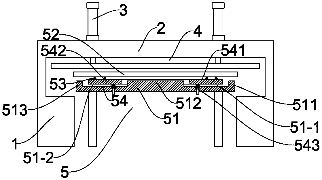
[0018] Such as figure 1 As shown, a molding press includes a frame 1, a beam 2 arranged on the frame 1, a hydraulic cylinder 3 arranged on the beam 2, a pressure bar 4 arranged at the telescopic end of the hydraulic cylinder 3 and The object stage 5 arranged under the pressure bar 4; the object stage 5 includes a relatively fixed bottom plate 51, and the bottom plate 51 is provided with a flexible carrier plate 52 for carrying workpieces and molds. A pulley 53 is disposed below the flexible carrier 52 , so that the flexible carrier 52 can be pulled out r...


PUM


Abstract

The present invention relates to a molding machine. It includes a frame, a crossbeam arranged on the frame, a hydraulic cylinder arranged on the crossbeam, a pressure bar arranged at the telescopic end of the hydraulic cylinder, and an object table arranged under the pressure bar; The object table includes a relatively fixed bottom plate, on which a flexible carrier plate for carrying workpieces and molds is arranged. In the present invention, a flexible carrier is provided, and pulleys are arranged at the bottom of the flexible carrier, so that the flexible carrier can be pulled out, thus changing the use of the traditional molding machine. board, and then the mold can be pressed by a molding machine, which avoids potential safety hazards.

Description

technical field [0001] The invention relates to a molding press and belongs to the technical field of proofing and cutting equipment. Background technique [0002] In the production of bags, it is often necessary to use cloth or sheets cut into various shapes. By sewing the cloth cut into various shapes to form a unique overall shape of the bag. In the prior art, a molding machine is usually used to cooperate with a mold to cut cloth or sheet material. When in use, the mold is placed on the cloth or sheet material, and the pressure of the molding machine is used to make the blade-like hard edge of the mold outline against the cloth or sheet. Material is cut. Yet the molding press of prior art needs cloth to be placed under the pressure head of molding machine earlier when using, then puts mold, finally controls molding machine. This method is not only cumbersome to operate, but also requires the operator to work under the pressure head of the press, which has potential sa...

Claims


Application Information

Patent Timeline
Patent Type & Authority Applications(China)
IPC IPC(8): D06H7/00
CPCD06H7/00
Inventor 陈洪
Owner 陈洪
Learn More