
Gear case ventilation structure and gear case

A ventilation structure and gear box technology, applied in belts/chains/gears, transmission parts, mechanical equipment, etc., can solve the problems of easy dust contamination, blocked breathing passages, etc., and achieve the effects of easy maintenance, improved waterproofing, and simple structure

Active Publication Date: 2018-03-13
ZHUZHOU ELECTRIC LOCOMOTIVE CO LTD
View PDF9 Cites 3 Cited by
  • Summary
  • Abstract
  • Description
  • Claims
  • Application Information

AI Technical Summary

Problems solved by technology

The disadvantage is that part of the oil mist will escape the gear box and condense around the respirator, which is easy to be contaminated with dust, and even more seriously, it will even block the breathing passage

Method used


Image

  • Gear case ventilation structure and gear case
  • Gear case ventilation structure and gear case
  • Gear case ventilation structure and gear case

Examples


Embodiment Construction

[0020] The present invention will be described in further detail below in conjunction with the accompanying drawings.

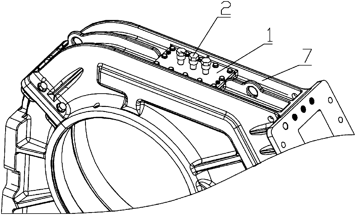
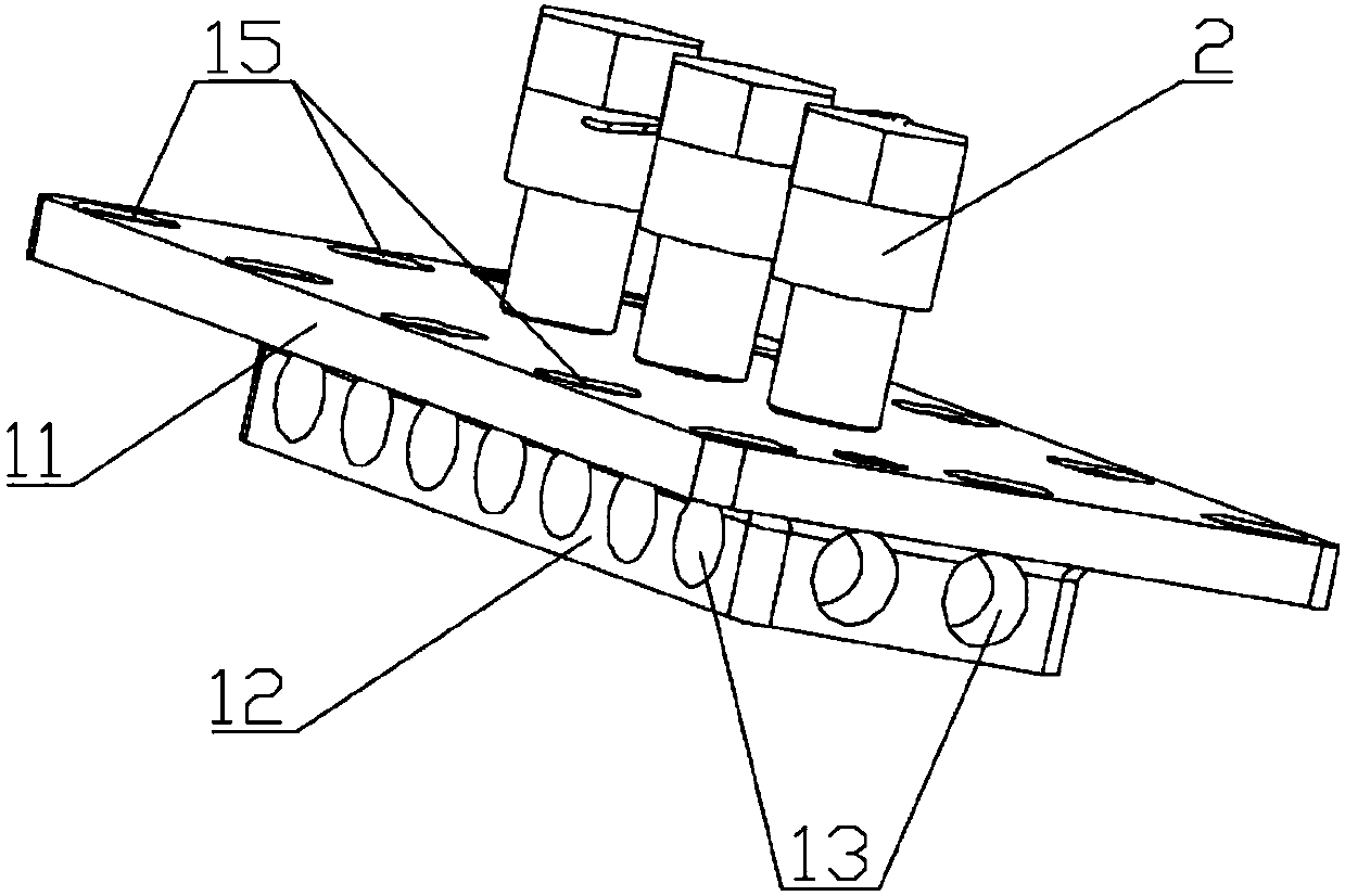
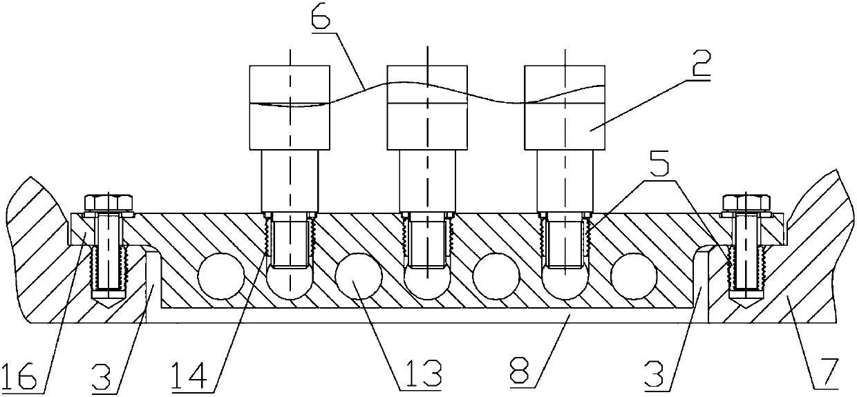
[0021] see Figure 1-5 , a gear box ventilation structure, which includes a ventilation cover 1 and a respirator 2 arranged on the ventilation cover 1, the ventilation cover 1 includes an upper cover 11 and a lower cover 12, the The upper cover plate 11 covers the lower cover plate 12, and the area where the upper cover plate 11 protrudes from the lower cover plate 12 is an installation skirt 16, and the ventilation cover plate 1 is installed on the On the gear box 7, the upper cover plate 11 covers the cover plate installation hole 8 on the gear box 7, the lower cover plate 12 is located in the cover plate installation hole 8 and the side of the lower cover plate 12 is in contact with the There is a ventilation gap 3 between the inner surfaces of the cover mounting holes 8, the lower cover 12 is provided with a ventilation hole 13 penetrating the side of th...


PUM


Abstract

The invention discloses a gear case ventilation structure and a gear case. The gear case ventilation structure comprises a ventilation cover plate and ventilators arranged on the ventilation cover plate; the ventilation cover plate comprises an upper-layer cover plate body and a lower-layer cover plate body, the lower-layer cover plate body is covered with the upper-layer cover plate body, and thearea, protruding out of the lower-layer cover plate body, of the upper-layer cover plate body is adopted as an installing skirt edge; and ventilation holes penetrating through the side faces of the lower-layer cover plate body are formed in the lower-layer cover plate body, and first installing holes are formed in the upper surface of the ventilation cover plate, communicate with the ventilationholes and are used for allowing the ventilators to be installed. According to the gear case ventilation structure, the honeycomb-shaped ventilation cover plate is formed through multiple ventilation holes, therefore, the distance from the interior of a gear case body to the outside is lengthened, oil mist can be coagulated in the honeycomb-shaped ventilation holes and then flows back into the gearcase, the condition that the oil mist escapes out of the gear case is reduced, and the functions of achieving ventilation but not allowing oil to pass are achieved on the mechanical structure.

Description

technical field [0001] The invention relates to the technical field of gear box ventilation structure, in particular to a gear box ventilation structure and a gear box. Background technique [0002] High-speed gearboxes, especially high-speed gearboxes for rail vehicles with a gear line speed of more than 40m / s, generally need to be equipped with a gearbox ventilation device to ensure the relative balance between the internal air pressure of the box and the external atmospheric pressure, so as to avoid excessive air pressure in the box. Large, resulting in oil leakage. The usual method is to directly drill the ventilation installation hole on the box body or the bearing seat, install the respirator, and the respirator is directly connected with the inside of the box body. During the high-speed operation of the gearbox, the interior of the gearbox is mostly a mixture of air and oil atomization. In order to ensure that the lubricating oil does not leak, the inside of the...

Claims


Application Information

Patent Timeline
Patent Type & Authority Applications(China)
IPC IPC(8): F16H57/027
CPCF16H57/027
Inventor 易兴利陈国胜张又孔沈龙江何烨祝贺邹文辉张冲谢加辉高彬肖泽华魏宏图郭庆升
Owner ZHUZHOU ELECTRIC LOCOMOTIVE CO LTD
Learn More