Transmission shaft body structure

A transmission shaft and housing technology, applied in the field of transmission shaft structure, can solve problems such as low work efficiency, unsuitability for industrialized large-scale production, unreasonable design of transmission shaft structure, etc., to achieve convenient implementation, reasonable structure design, and stable installation Effect

Inactive Publication Date: 2018-03-13
高荣江
View PDF0 Cites 0 Cited by
  • Summary
  • Abstract
  • Description
  • Claims
  • Application Information

AI Technical Summary

Problems solved by technology

[0002] The existing drive shaft structure design is unreasonable, the work efficiency is low, and it is not suitable for industrialized mass production

Method used


Image

  • Transmission shaft body structure

Examples


Embodiment Construction

[0009] The present invention will be further explained below in conjunction with the drawings and embodiments.

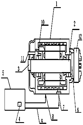
[0010] Such as figure 1 As shown, a transmission shaft structure includes a transmission housing 1 and a transmission shaft 2 arranged inside the transmission housing 1. A transmission shaft motor 3 is provided on one side of the transmission housing 1, and the transmission shaft The body motor 3 is electrically connected to the transmission shaft body 2, and one end of the transmission shaft body 2 is sleeved with a propulsion shaft 6, the propulsion shaft 6 is movably provided with a three-jaw chuck 12, and the transmission housing 1 is provided with The water inlet 7 and the water outlet 8, the water inlet 7 and the water outlet 8 are connected to the circulating condensate water tank 5 through the pipe body 9, the circulating water pump 4 is provided in the circulating condensate water tank 5, and the transmission shaft body 2 is provided with At least one bearing...


PUM


Abstract

The invention discloses a transmission shaft body structure comprising a transmission housing (1) and a transmission shaft body (2) disposed in the transmission housing (1). A transmission shaft bodymotor (3) is arranged on one side of the transmission housing (1) and electrically connected with the transmission shaft body (2); one end of the transmission shaft body (2) is in a sleeved connectionwith a propelling shaft (6); a three-paw chuck (12) is movably arranged on the propelling shaft (6); a water inlet (7) and a water outlet (8) are arranged on the transmission housing (1); the water inlet (7) and the water outlet (8) are connected with a circulating condensate water tank (5) via pipeline bodies (9); and a circulating water pump (4) is disposed in the circulating condensate water tank (5). The transmission shaft body structure is advantaged by rational structure and energy consumption reduction.

Description

Technical field [0001] The invention relates to a transmission device, in particular to a transmission shaft body structure. Background technique [0002] The existing transmission shaft body structure design is unreasonable, the work efficiency is low, and it is not suitable for industrialized mass production. Summary of the invention [0003] The problem to be solved by the present invention is to provide a transmission shaft body structure. [0004] In order to solve the above problems, the present invention provides a transmission shaft body structure, which includes a transmission housing and a transmission shaft body arranged inside the transmission housing. A transmission shaft motor is provided on one side of the transmission housing. The shaft motor is electrically connected to the transmission shaft body, one end of the transmission shaft body is sleeved with a propulsion shaft, the propulsion shaft is movably provided with a three-jaw chuck, and the transmission housing ...

Claims


Application Information

Patent Timeline
Patent Type & Authority Applications(China)
IPC IPC(8): F16H57/04F16C3/02H02K7/10
CPCF16H57/0412F16C3/02H02K7/10
Inventor 高荣江
Owner 高荣江
Why Eureka
Try Eureka