High-voltage cable oscillatory wave partial discharge test system

A high-voltage cable and testing system technology, applied in the direction of testing dielectric strength, measuring electricity, measuring devices, etc., can solve the problems of no tightening measures, affecting installation efficiency, and unstable installation, and achieves high connection firmness and structure. Simple and effective in eliminating security risks

Active Publication Date: 2018-03-13
杭州盛能电力科技有限公司
View PDF9 Cites 5 Cited by
  • Summary
  • Abstract
  • Description
  • Claims
  • Application Information

AI Technical Summary

Problems solved by technology

Due to the different test objects, the number of high-voltage reactors needs to be flexibly configured on site. In order not to affect the performance of the high-voltage reactors, the high-voltage reactors are generally stacked and placed. The high-voltage reactors are simply stacked and no fastening measures are taken. , not only there is a certain potential safety hazard, but also it is difficult to locate during the installation process, and it is easy to drop, which affects the installation efficiency
Therefore, the existing technology has the problems of troublesome installation and insecure installation

Method used


Image

  • High-voltage cable oscillatory wave partial discharge test system
  • High-voltage cable oscillatory wave partial discharge test system
  • High-voltage cable oscillatory wave partial discharge test system

Examples


Embodiment Construction

[0020] The present invention will be further described below in conjunction with the accompanying drawings and embodiments, but not as a basis for limiting the present invention.

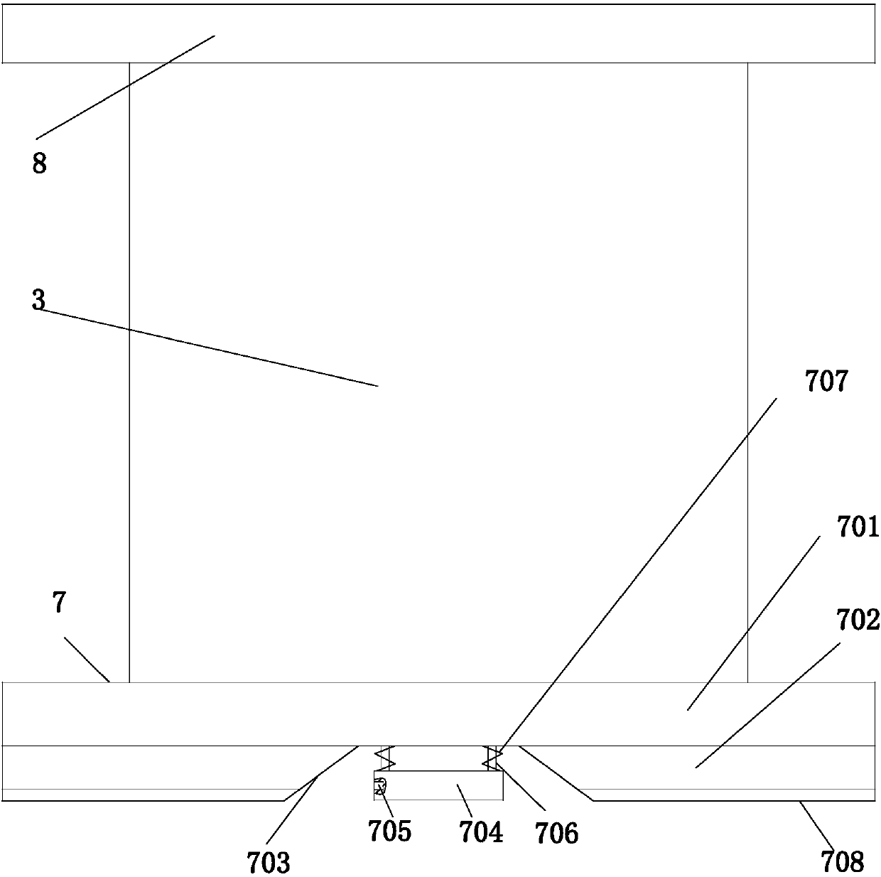
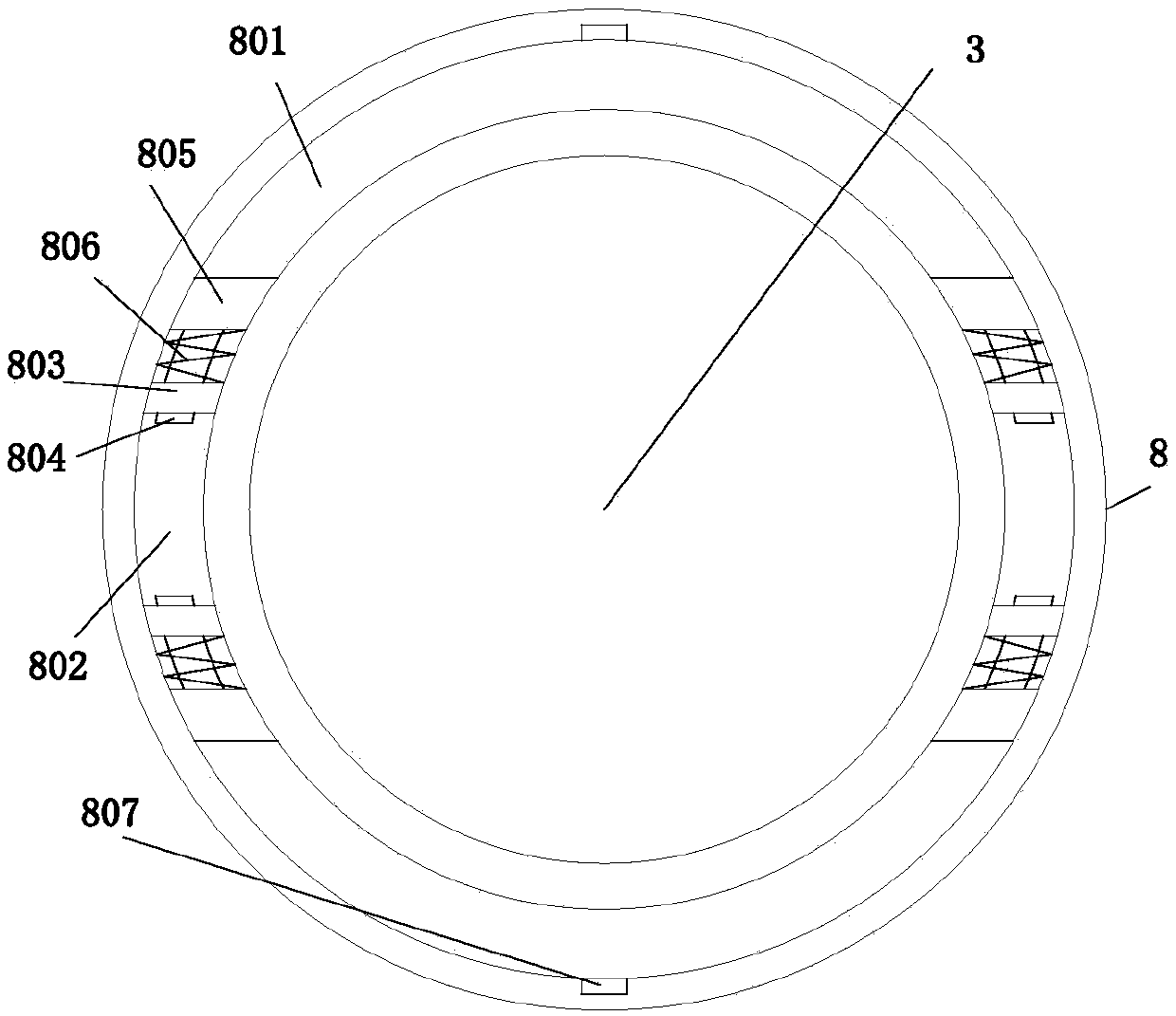
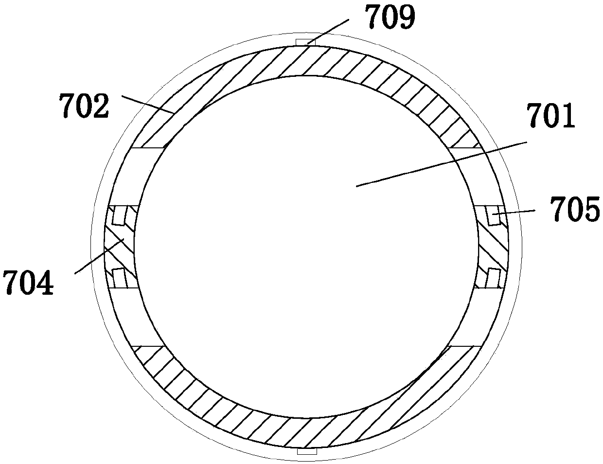
[0021] Example. A high-voltage cable oscillatory wave partial discharge test system, which is composed of Figure 1 to Figure 6 As shown, it includes a high-voltage DC power supply 1, a high-voltage switch 2, a high-voltage reactor 3, a capacitor voltage divider 4, a data acquisition and analysis unit 5, and a partial discharge coupling unit 6. The bottom of the high-voltage reactor 3 is provided with a base 7, and the high-voltage reactor The top of the device 3 is provided with a card seat 8; the base 7 includes a base 701 fixed to the high voltage reactor 3, and two symmetrically arranged ring-shaped fixing seats 702 are arranged under the base 701, and the two ends of the ring-shaped fixing seat 702 are Inclined surface structure 703, limit plate 704 is arranged between annular fixed seat 702, ...


PUM


Abstract

The invention discloses a high-voltage cable oscillatory wave partial discharge test system which comprises a high-voltage DC power supply, a high-voltage switch, a high-voltage reactor, a capacitivevoltage divider, a data acquisition analysis unit and an partial discharge coupling unit. The bottom of the high-voltage reactor is provided with a base. The top of the high-voltage reactor is provided with a clamping seat. The base includes a substrate base fixed to the high-voltage reactor. Two symmetrically arranged annular fixing seats are arranged below the substrate base. Both ends of each annular fixing seat are inclined structures. A stopping plate is arranged between the annular fixing seats. Positioning holes are arranged on both end faces of the stopping plate. A telescopic rod is arranged between the stopping plate and the substrate base. A spring sleeves the telescopic rod. The high-voltage cable oscillatory wave partial discharge test system is able to reduce potential safetyhazards and improve installation efficiency.

Description

technical field [0001] The invention relates to a cable testing device, in particular to a high-voltage cable oscillatory wave partial discharge testing system. Background technique [0002] With the improvement of power supply level requirements, domestic power supply units are constantly improving the detection methods of power equipment, and have gradually upgraded from the extensive inspection and fault repair mode to the status monitoring mode of power equipment, that is, through online or offline The way of monitoring can discover the defects of power equipment, and maintain the potential failure points in advance, so as to take precautions. The off-line oscillatory wave partial discharge test of power cables is a method widely used in the world at present. A high-voltage cable oscillatory wave partial discharge test system is mainly composed of a high-voltage power supply, a high-voltage switch, a high-voltage reactor, and a capacitor voltage divider. and data collec...

Claims


Application Information

Patent Timeline
Patent Type & Authority Applications(China)
IPC IPC(8): G01R31/12
CPCG01R31/1272Y04S10/52
Inventor 斯应昌
Owner 杭州盛能电力科技有限公司
Why Eureka
Try Eureka