
Sealing apparatus, bipolar battery and single battery

A sealing device and sealing end cap technology, applied in sealing materials, lead-acid batteries, battery pack components, etc., can solve the problems of reducing battery discharge performance, battery discharge voltage, and battery temperature, so as to improve discharge performance and The effect of service life, reducing internal resistance and suppressing temperature rise

Active Publication Date: 2018-03-13
朱学军
View PDF7 Cites 0 Cited by
  • Summary
  • Abstract
  • Description
  • Claims
  • Application Information

AI Technical Summary

Problems solved by technology

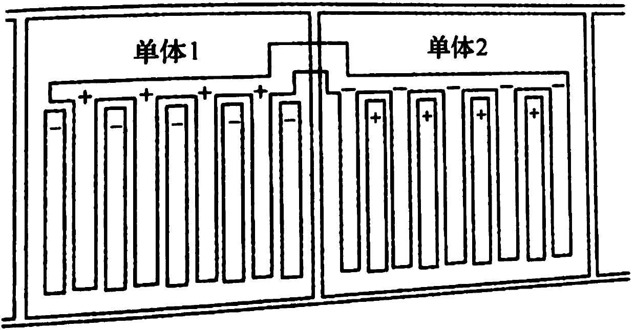
like figure 1 As shown, when multiple monomers are connected in series, a partition wall is first formed between the monomers, and then the pole plates of a certain polarity in one of the monomers are connected in parallel to form a pole group, which is opposite to that of the adjacent monomer. Polar pole groups are connected together by through-wall welding or cross-bridge welding. The production cost is high, the connection path between each monomer is long, and the resistance is large. Therefore, a large amount of Joule heat will be generated when the battery is discharged, causing the battery temperature to rise, resulting in The discharge voltage of the battery is reduced, which greatly reduces the discharge performance of the battery

Method used


Image

  • Sealing apparatus, bipolar battery and single battery
  • Sealing apparatus, bipolar battery and single battery
  • Sealing apparatus, bipolar battery and single battery

Examples


Embodiment 1

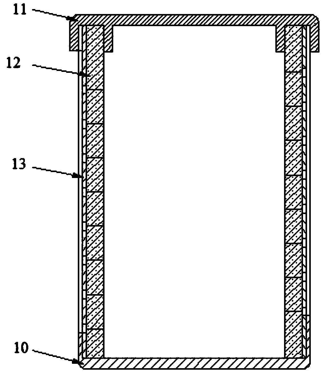
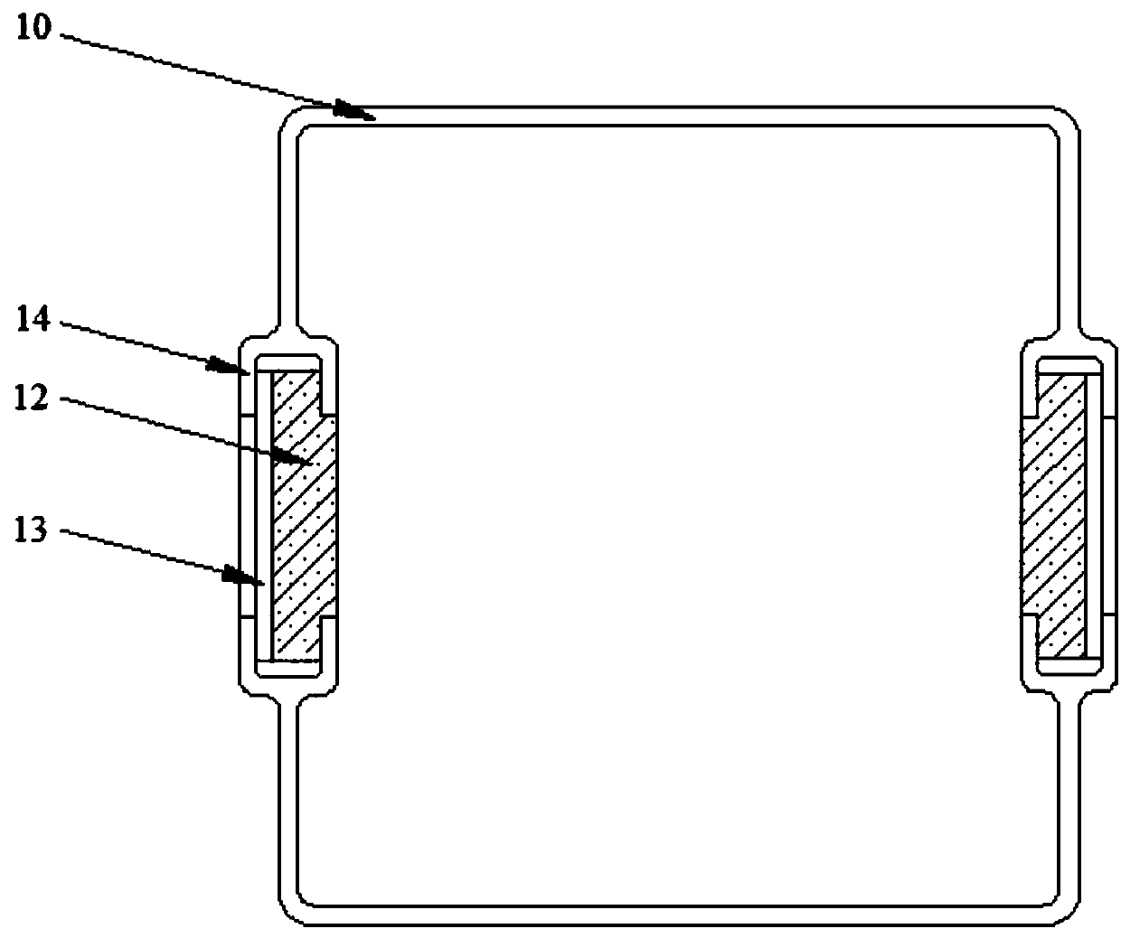
[0042] Such as figure 2 and image 3 As shown, a sealing device for a battery plate, the sealing device 1 includes: a tank body 10, a sealing upper cover 11 covering the tank body, and a soft adsorption strip 12, wherein,

[0043] Described groove body 10 comprises two oppositely arranged groove walls, and the two ends of each described groove wall are all provided with a groove wall positioning groove 14, and the groove of described groove wall positioning groove 14 of the same end of two described groove walls The mouths are opposite, and the end face of the groove wall positioning groove 14 is flush with the notch of the groove body 10 .

[0044]The soft adsorption strip 12 is adsorbed with a liquid adhesive and solidified, and the two ends of the soft adsorption strip 12 are embedded in a pair of groove wall positioning grooves 14 opposite to the notch, and multiple layers are embedded in the grooves. The soft adsorption strip 12 in the wall positioning groove 14 and th...

Embodiment 2

[0050] Such as Figure 5 and Figure 6 As shown, a bipolar battery includes: the sealing device 1, the positive plate 2, the bipolar plate 3, the negative plate 4 and the separator 5 in multiple embodiments 1, wherein,

[0051] The sealing device 1 includes positive sealing devices and at least one bipolar sealing device connected in series in sequence, and the sealing end caps between adjacent sealing devices 1 are the same sealing end cap, and each of the sealing devices 1 The sealed space is filled with electrolyte;

[0052] The sealing device matched with the positive electrode plate 2 is the positive sealing device, a plurality of the positive electrode plates 2 are parallel to the bottom of the groove and stacked in the groove body of the positive sealing device 1, each of the One end of the positive plate 2 is a positive plate extension 21, and the other end of the positive plate 2 is a positive plate built-in end 22. Each of the positive plate extensions 21 is connec...

Embodiment 3

[0071] Such as Figure 7 and Figure 8 As shown, a single battery, the single battery includes: the sealing device 1 described in embodiment 1, the positive plate 2, the negative plate 4 and the separator 5, wherein,

[0072] One end of each positive plate 2 is a positive plate extension 21, the other end of the positive plate 2 is a positive plate built-in end 22, and one end of each negative plate 4 is a negative plate extension 41. The other end of the plate 4 is the built-in end 42 of the negative plate;

[0073] A plurality of positive plates 2 are parallel to the bottom of the tank and stacked in the tank body of the sealing device 1, and each of the positive plate extensions 21 is absorbed from the adjacent soft material of the sealing end cap on the same side. The gap between the strips 12 protrudes; one negative plate 4 is arranged parallel to the bottom of the groove between two adjacent positive plates 2, and each negative plate extension 41 is drawn from the othe...


PUM


Abstract

The invention discloses a sealing apparatus, a bipolar battery and a single battery. The sealing apparatus comprises a groove body, soft adsorption strips and a sealing upper cover which covers the upward side of the groove body; the groove body comprises two oppositely arranged groove walls; a groove wall positioning groove is formed in each of the two ends of each groove wall separately; a liquid binder is adsorbed and cured in each soft adsorption strip; the two ends of each soft adsorption strip are embedded into a pair of groove wall positioning grooves with opposite groove openings; multiple soft adsorption strips which are embedded into the groove wall positioning grooves in a stacked manner and the groove wall positioning grooves form a sealing end cover on the port of the groove body; the soft adsorption strips and the groove wall positioning grooves, the adjacent soft adsorption strips, the soft adsorption strip on the uppermost layer and the sealing upper cover, and the softadsorption strip on the lowest layer and the groove bottom are all in interference fit; and the groove body, the sealing end cover and the sealing upper cover form a sealed space. By virtue of the sealing apparatus, the connecting path of the adjacent single batteries can be greatly shortened, thereby lowering the internal resistance of the batteries, controlling temperature rise of the batteries, and further improving the discharging performance and prolonging the service life of the batteries.

Description

technical field [0001] The invention relates to the field of design and manufacture of lead-acid storage batteries, a sealing device, a bipolar battery and a single battery. Background technique [0002] Lead-acid batteries are generally composed of multiple single cells, and each single cell is separated by a plastic partition for injection molding. Each single battery is composed of positive and negative polar plates. Such as figure 1 As shown, when multiple monomers are connected in series, a partition wall is first formed between the monomers, and then the pole plates of a certain polarity in one of the monomers are connected in parallel to form a pole group, which is opposite to that of the adjacent monomer. Polar pole groups are connected together by through-wall welding or cross-bridge welding. The production cost is high, the connection path between each monomer is long, and the resistance is large. Therefore, a large amount of Joule heat will be generated when the...

Claims


Application Information

Patent Timeline
Patent Type & Authority Applications(China)
IPC IPC(8): H01M2/08H01M10/12H01M50/184H01M50/186
CPCH01M10/12H01M50/183Y02E60/10Y02P70/50
Inventor 朱学军
Owner 朱学军
Learn More