Protection door assembly turnover plate and protection door assembly method
An assembly method and technology for protecting the door, which are applied in the directions of electrical components, circuits, connections, etc., can solve problems such as low assembly efficiency, and achieve the effect of improving assembly efficiency and simplifying the installation process.
- Summary
- Abstract
- Description
- Claims
- Application Information
AI Technical Summary
Problems solved by technology
Method used
Image

Examples
Embodiment 1
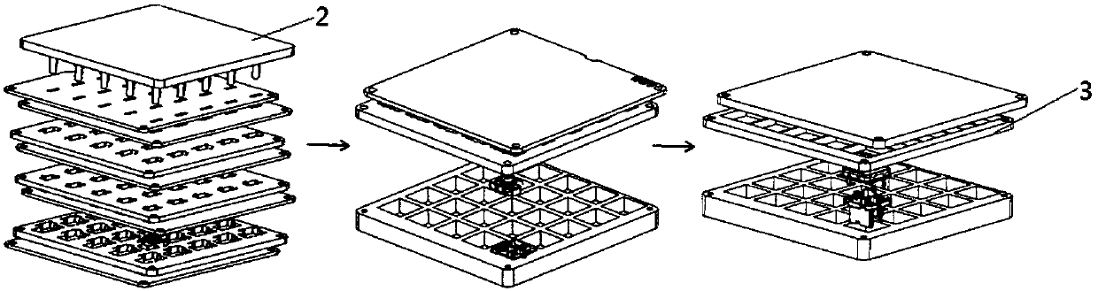
[0052] see Figure 1-3 Embodiment 1 of the present application shows an assembly flap for a protective door, and the assembly flap includes: a plywood 1;
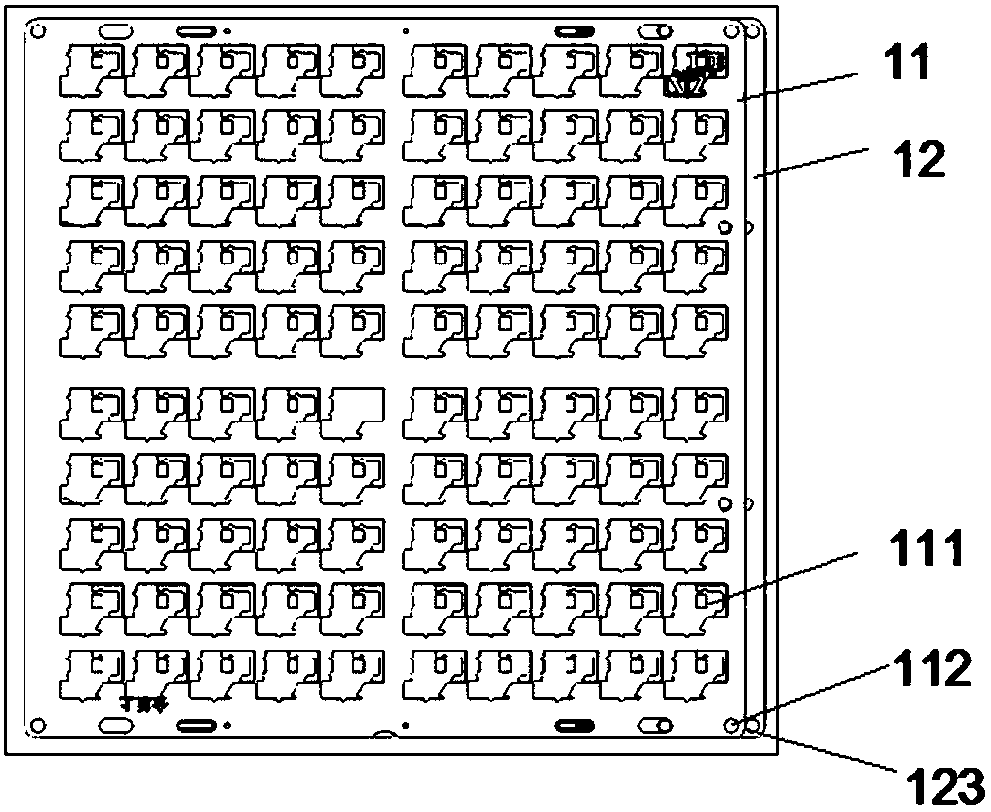
[0053] The plywood 1 includes an upper plywood 11 and a lower plywood 12, the upper plywood 11 and the lower plywood 12 are stacked up and down, and can be dislocated and moved;
[0054] Wherein, the upper closing plate 11 is provided with a plurality of loading holes 111, and the loading holes 111 include the loading area of the two-pole assembly, the loading area of the three-pole assembly and the loading area of the spring, and the length of the spring loading area is greater than the natural length of the spring;
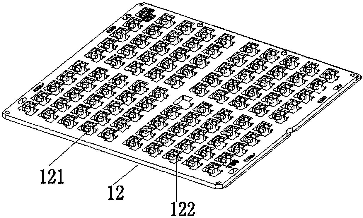
[0055] The lower plywood 12 is provided with a plurality of fixing components 121 and through holes 122 of the lower plywood; The position of corresponds to the position of the loading hole 111.
[0056] When installing, place the two-pole assembly, three-pole assembly and spring in the loading hole 1...
Embodiment 2
[0058] see Figure 4 and Figure 5 , the assembled flap also includes: a limiting plate 3, a base carrier 4 and an upper cover carrier 5;
[0059] The base carrier 4 is provided with a plurality of base storage holes 41, and when the plywood overlaps with the base carrier 4, the positions of the base storage holes 41 correspond to the positions of the loading holes 111;
[0060] The upper cover carrier plate 5 is provided with a plurality of upper cover storage holes 51, and when the plywood overlaps with the upper cover carrier plate 5, the positions of the upper cover storage holes 51 correspond to the positions of the loading holes 111 ;
[0061] During the installation of the protective door, the plywood carrying the assembly components is buckled upside down on the base carrier plate 4 carrying the base, because the position of the through hole 122 of the lower plywood corresponds to the position of the loading hole 111, and the lower plywood can be passed through The ...
Embodiment 3
[0065] see Image 6 , Embodiment 3 of the present application shows an assembly flap for a protective door. On the basis of the assembly flap described in Embodiment 1, the assembly flap further includes a top plate 2;
[0066] The top plate 2 is provided with a plurality of props 21, and the props 21 pass through the through holes 122 of the lower plywood, and the top plate 2 is pinned to the lower plywood 12.
[0067] Concretely, place the plywood undercut carrying the assembly components on the base carrier plate 4 carrying the base, place the top plate 2 on the lower plywood carrying the assembly components, and make the top column 21 pass through the lower plywood. Hole 122 , because the position of the through hole 122 of the lower plywood corresponds to the position of the loading hole 111 , therefore, the jack post 21 passes through the through hole 122 of the lower plywood and abuts on the protective door element.
[0068] The top column 21 passes through the through...
PUM
 Abstract
Description
Claims
Application Information
 - R&D
- Intellectual Property
- Life Sciences
- Materials
- Tech Scout
- Unparalleled Data Quality
- Higher Quality Content
- 60% Fewer Hallucinations
Browse by: Latest US Patents, China's latest patents, Technical Efficacy Thesaurus, Application Domain, Technology Topic, Popular Technical Reports.
© 2025 PatSnap. All rights reserved.Legal|Privacy policy|Modern Slavery Act Transparency Statement|Sitemap|About US| Contact US: help@patsnap.com