

Spherical camera easy to clean
A spherical camera and cleaning technology, applied in cleaning methods and tools, cleaning methods using tools, image communication, etc., can solve the problems of poor self-cleaning effect of spherical cameras, to prevent excessive accumulation of rainwater, good cleaning effect, The effect of improving the cleaning effect
- Summary
- Abstract
- Description
- Claims
- Application Information
AI Technical Summary
Problems solved by technology
Method used
Image

Examples
Embodiment 1
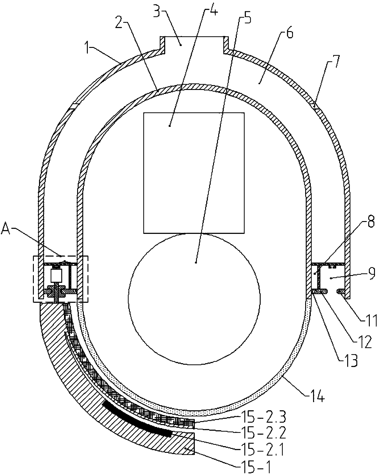
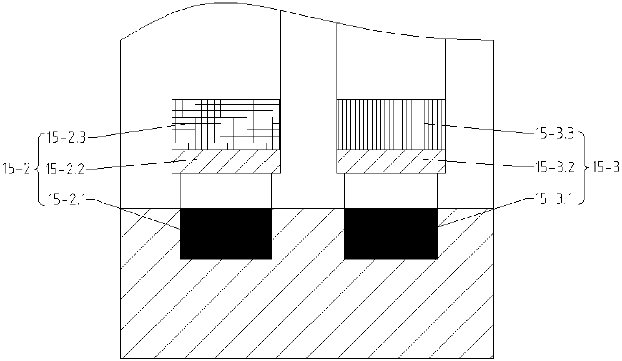
[0021] An easy-to-clean dome camera, comprising a protective cover, a camera 5 and a control system 4 arranged inside the protective cover, the protective cover is divided into an upper waterproof cover 2 and a lower glass cover 14, and is characterized in that: the outer cover of the waterproof cover 2 There is an outer cover 1, a gap between the waterproof cover 2 and the outer cover 1, an opening 3 is opened at the top of the outer cover 1, and an outer ring slide rail 11 and an inner ring slide rail are respectively arranged on the inner wall of the bottom end of the outer cover 1 and the outer wall of the waterproof cover 2 12. A power device 21 is provided between the outer ring slide rail 11 and the inner ring slide rail 12. The lower end of the power device 21 is connected to the cleaning device 15. The cleaning device 15 includes an arc-shaped cleaning arm 15-1, and the upper surface of the cleaning arm 15-1 is A cleaning sponge mechanism 15-2 and a cleaning brush mech...
Embodiment 2
[0025] This embodiment improves on the basis of Embodiment 1:
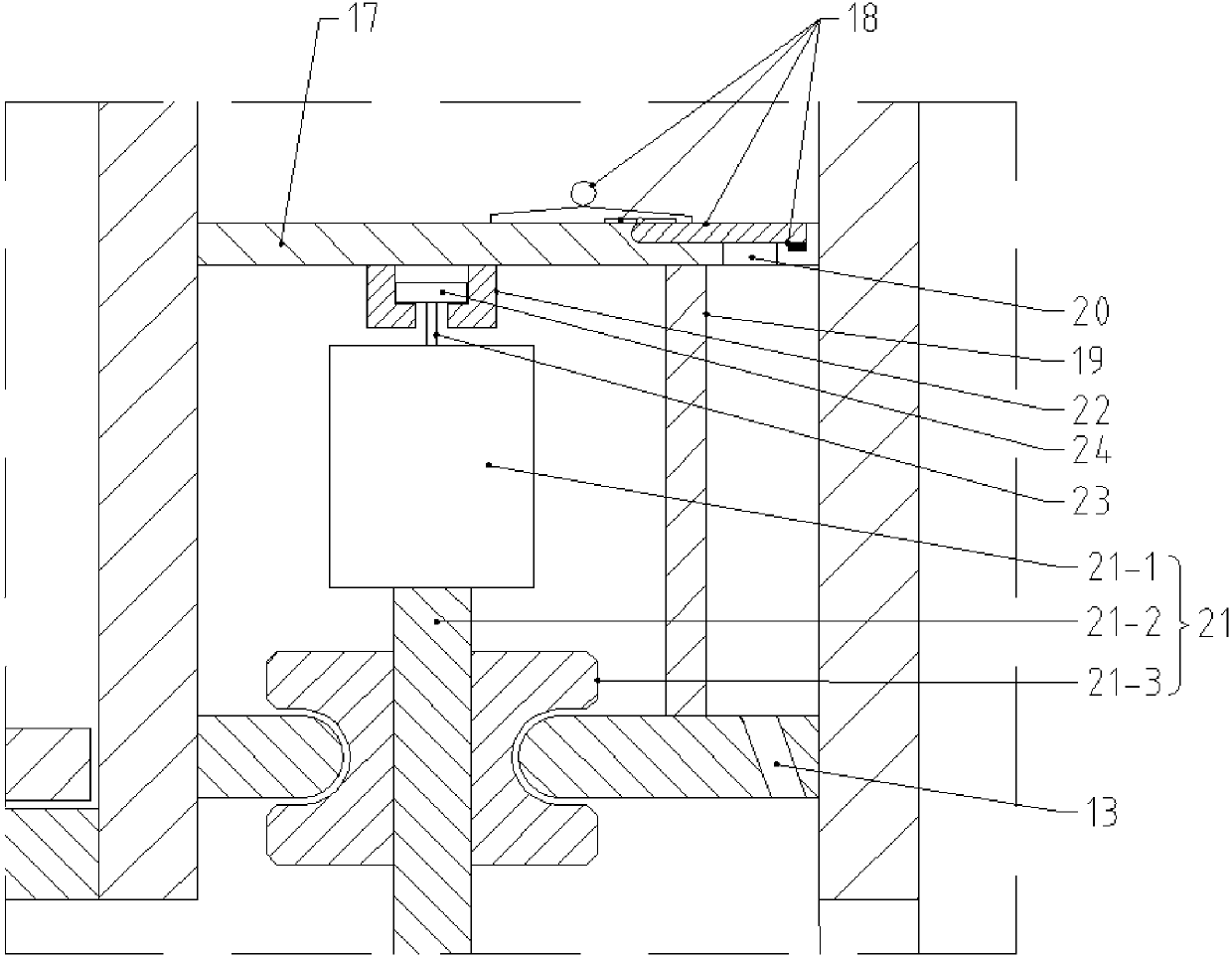
[0026] The upper surface of the inner ring slide rail 12 is vertically provided with an annular baffle a19, and the upper end of the annular baffle a19 is horizontally connected with an annular baffle b17. The annular baffle a19 and the annular baffle b17 divide the gap into a water storage chamber 6, a water inlet The chamber 8 and the power chamber 9 are provided with a water inlet 20 connected to the water inlet chamber 8 on the annular baffle b17. The water inlet 20 is provided with an opening and closing device 18 electrically connected to the control system 4. The inner ring slide rail 12 is vertically A plurality of through holes 13 communicating with the water inlet chamber 8 are opened, and the power device 21 is arranged in the power chamber 9 .
[0027] The advantages of the above improvements are: in rainy days, the opening at the top of the outer cover can be used to collect rainwater and store it in ...
Embodiment 3
[0029] This embodiment is improved on the basis of the above embodiments:
[0030] The power unit 21 includes a rotating shaft 21-2 vertically arranged between the outer ring slide rail 11 and the inner ring slide rail 12, the upper end of the rotating shaft is connected to the motor 21-1, and the rotating shaft 21-2 is sleeved with the outer ring slide rail 11, the inner The grooved wheel 21-3 matched with the ring slide rail 12, the lower end of the rotating shaft 21-2 is connected with the cleaning device 15, and the motor 21-1 is electrically connected with the control system 4.
PUM
 Abstract
Description
Claims
Application Information