Multifunctional aluminum alloy product heat radiating device
A technology of heat dissipation equipment and aluminum alloy, applied in the field of heat dissipation equipment, can solve problems such as poor heat dissipation effect, inconvenient heat dissipation of aluminum alloy products, and visual impact of staff, and achieve the effect of increasing heat dissipation speed
- Summary
- Abstract
- Description
- Claims
- Application Information
AI Technical Summary
Problems solved by technology
Method used
Image

Examples
Embodiment
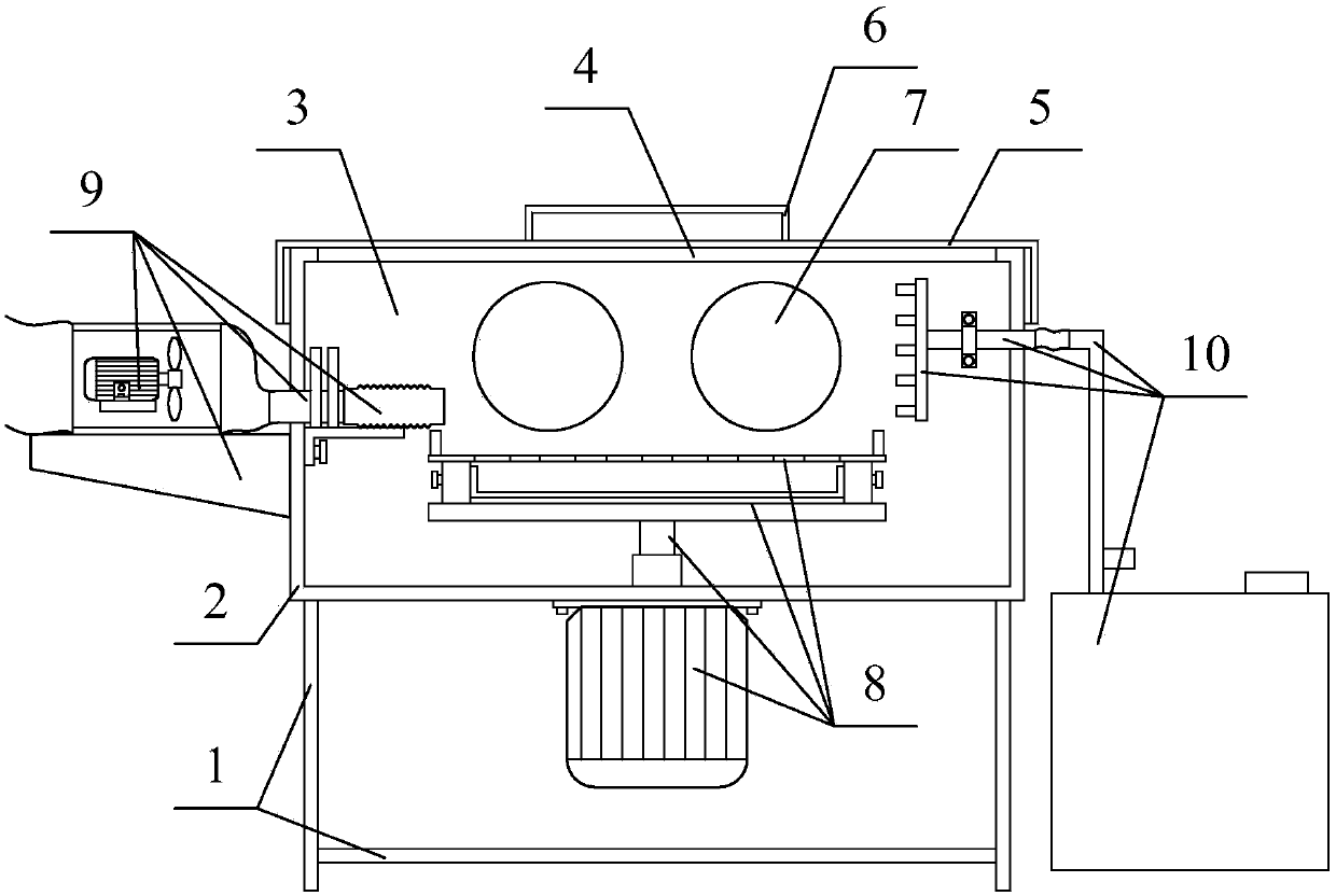
[0029] as attached figure 1 to attach Figure 4 shown
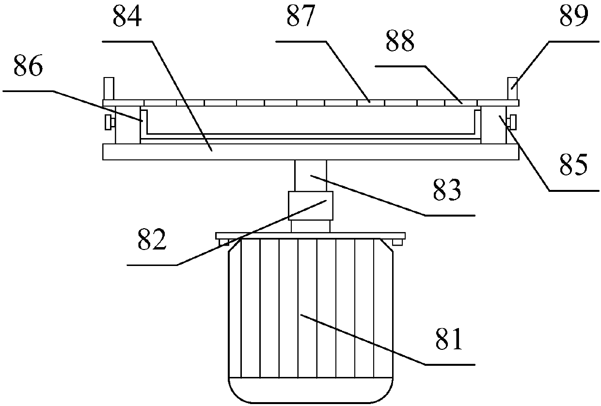
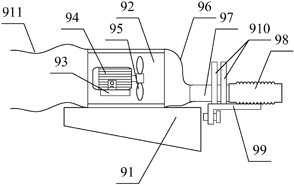
[0030] The present invention provides a multi-functional heat dissipation device for aluminum alloy products, which includes a support frame 1, a working box 2, a box cavity 3, an inlet and outlet 4, a sealing cover 5, a handle 6, a cooling fan 7, a rotating disk structure 8, and a suction pipe Structure 9 and cooling spray box structure 10, the working box 2 is welded on the top of the support frame 1; the box cavity 3 is opened inside the working box 2; The sealing cover 5 is socketed on the top of the working box 2; the handle 6 is welded on the upper surface of the sealing cover 5; The rotating disk structure 8 bolts are installed on the lower surface of the support frame 1; the suction pipe structure 9 is welded on the upper left part of the working box 2; the cooling spray box structure 10 is welded on the upper right part of the working box 2; The rotating disc structure 8 includes a rotating motor 81, a couplin...
PUM
 Abstract
Description
Claims
Application Information
PatSnap Eureka turns technology decisions into work you can execute. Powered by our Innovation Knowledge Graph, it runs expert workflows across engineering, life sciences, materials and intellectual property. Get your review-ready output in minutes.


