
Circulated cooling radiation screen

A circulating cooling and radiation screen technology, applied in the field of radiation screens, can solve the problems of radiation screen temperature difference, reduce cooling efficiency, and narrow assembly space, etc., and achieve the effect of small temperature difference of radiation screen, fast cooling speed and long transmission distance

Active Publication Date: 2017-05-17
SHANDONG AOXIN MEDICAL TECH CO LTD
View PDF6 Cites 5 Cited by
  • Summary
  • Abstract
  • Description
  • Claims
  • Application Information

AI Technical Summary

Problems solved by technology

[0003] The prior art has the following disadvantages: 1. When the distance between the cold head and the radiation screen is relatively long, and a certain amount of cold conduction needs to be ensured, the used cold conduction copper braid needs to become thicker and longer, so that not only It will cause the assembly space to be narrow, increase the volume of the magnet, and also make the copper flange connected to the cold head bear the weight of the copper braid, making it difficult to ensure the matching size of the copper flange and the cold head. The cooling efficiency is reduced; 2. The cold energy is transmitted from the local to the whole through solid conduction inside the radiation screen. Therefore, when the area of ​​the radiation screen is large, there will be an obvious temperature difference on the radiation screen, which will affect the protection of the radiation screen. Radiation effects have a certain effect

Method used


Image

  • Circulated cooling radiation screen
  • Circulated cooling radiation screen

Examples


Embodiment Construction

[0022] In order to facilitate the understanding of those skilled in the art, the present invention will be further described with reference to the accompanying drawings.

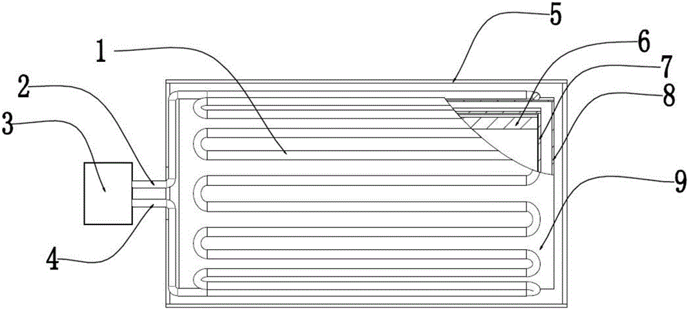
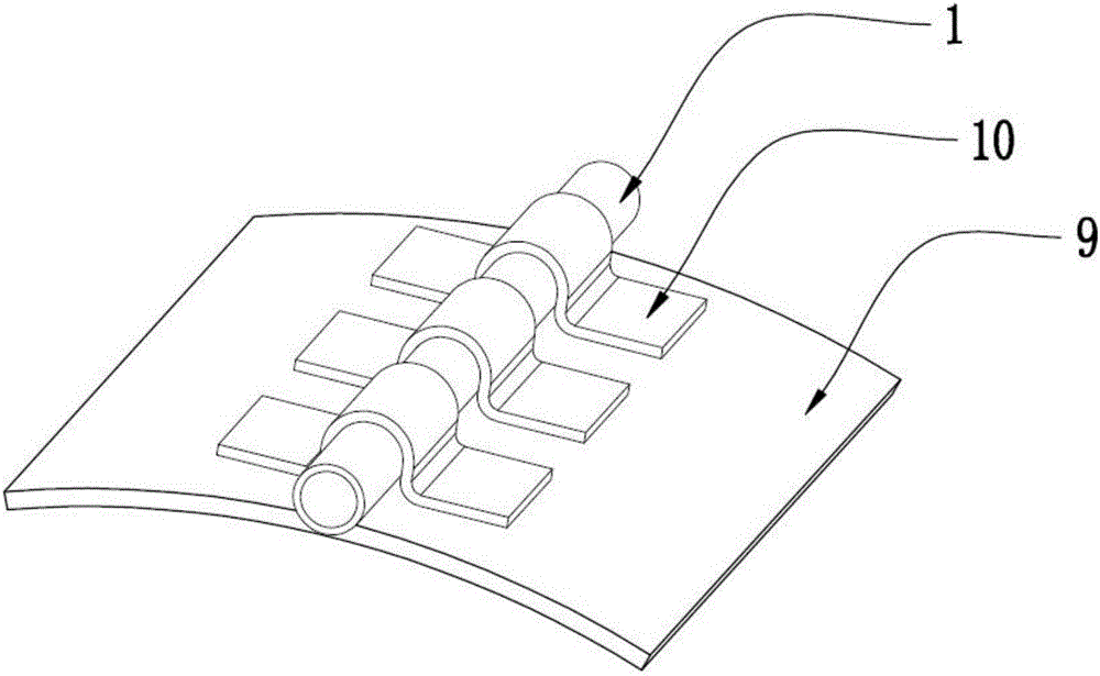
[0023] figure 1 It is a schematic diagram of the overall structure of the present invention. The outside of the room temperature Dewar 5 is the atmosphere and the inside is vacuum; the low temperature Dewar 7 is in a vacuum environment sealed by the room temperature Dewar 5, and the low temperature Dewar 7 is filled with liquid helium (-268.9°C) The superconducting coil 6 is immersed in liquid helium. The present invention is installed between the room temperature Dewar 5 and the low temperature Dewar 7, and includes a radiation screen outer tube 9. Both ends of the radiation screen outer tube 9 are provided with radiation screen end plates 8 In order to seal, a helium tube group is provided on the outer surface of the radiation shield outer tube 9. The helium tube group includes at least one helium tube 1, and ...


PUM


Abstract

The invention discloses circulated cooling radiation screen, and belongs to the technical field of superconducting magnet cooling. The screen comprises a radiation screen outer cylinder. Two ends of the radiation screen outer cylinder are provided with radiation screen end plates and sealing. The outer surface of the radiation screen outer cylinder is provided with a helium gas pipe group, which comprises at least one helium gas pipe. The helium gas pipe is distributed in S-shape on the outer surface of the radiation screen outer cylinder. According to the circulated cooling radiation screen, the helium gas pipe distributed on the outer surface of the radiation screen outer cylinder can effectively absorb the heat of the radiation screen outer cylinder and radiation screen end plates, and therefore the internal low temperature environment of the radiation screen outer cylinder can be effectively guaranteed. Compared with the prior art of copper braid structure, the cooling speed is faster. The helium gas pipe is distributed in S-shape on the outer surface of the radiation screen outer cylinder, can uniformly absorb the heat of the radiation screen outer cylinder. Compared with the prior art of the copper braid, the circulated cooling radiation screen has the advantages of not only being compact in structure, longer in transmission distance, but also capable of reducing the temperature difference of the radiation screen outer cylinder.

Description

Technical field [0001] The invention relates to the technical field of superconducting magnet cooling, in particular to a circulating cooling radiation screen. Background technique [0002] Low-temperature superconducting magnets are made using the characteristics of superconducting wires with zero resistance at low temperatures. To maintain the low-temperature environment required for the operation of superconducting magnets, it is necessary to reduce the radiation heat transfer of the external environment to the low-temperature Dewar. Installing a radiant screen is a way to greatly reduce radiant heat transfer. Therefore, the radiation screen is an important part of the cryogenic superconducting magnet, and it is also one of the key technologies to realize the "zero volatilization" of the cryogenic magnet. At present, the conventional radiation screen is made of aluminum or copper plate. The radiation screen is connected with the primary cold head of the GM refrigerator with a...

Claims


Application Information

Patent Timeline
IPC IPC(8): H01F6/04
CPCH01F6/04
Inventor 王兆连李培勇张义廷程东芹邵延海
Owner SHANDONG AOXIN MEDICAL TECH CO LTD
Learn More