Camera calibration system and calibration method thereof

A camera calibration and calibration method technology, applied in the camera calibration system and its calibration field, can solve the problems of misoperation, poor calibration flexibility, time-consuming and inconvenient repeated operation, etc.

Active Publication Date: 2018-03-16
SHANGHAI JIAO TONG UNIV
View PDF10 Cites 8 Cited by
  • Summary
  • Abstract
  • Description
  • Claims
  • Application Information

AI Technical Summary

Problems solved by technology

However, in many cases, it is not necessary to calibrate the hand-eye relationship between the camera and the robot, and the robot is only used to calibrate the internal parameters of the camera; and the camera calibration using the robot not only needs to customize the fixed fixture at the end of the camera and the robot, but also makes the calibration more flexible. Poor, if there is no robot at the work site, calibration cannot be carried out; moreover, since the pose of the end of the robot is directly controlled instead of the pose of the camera, it is easy to misuse when doing rotation, even if the calibration plate (reference object) exceeds The field of view of the camera needs to be compensated by moving the robot so that the calibration plate (reference object) returns to the field of view. Repeated operations are time-consuming and inconvenient

Method used


Image

  • Camera calibration system and calibration method thereof
  • Camera calibration system and calibration method thereof
  • Camera calibration system and calibration method thereof

Examples


Embodiment 1

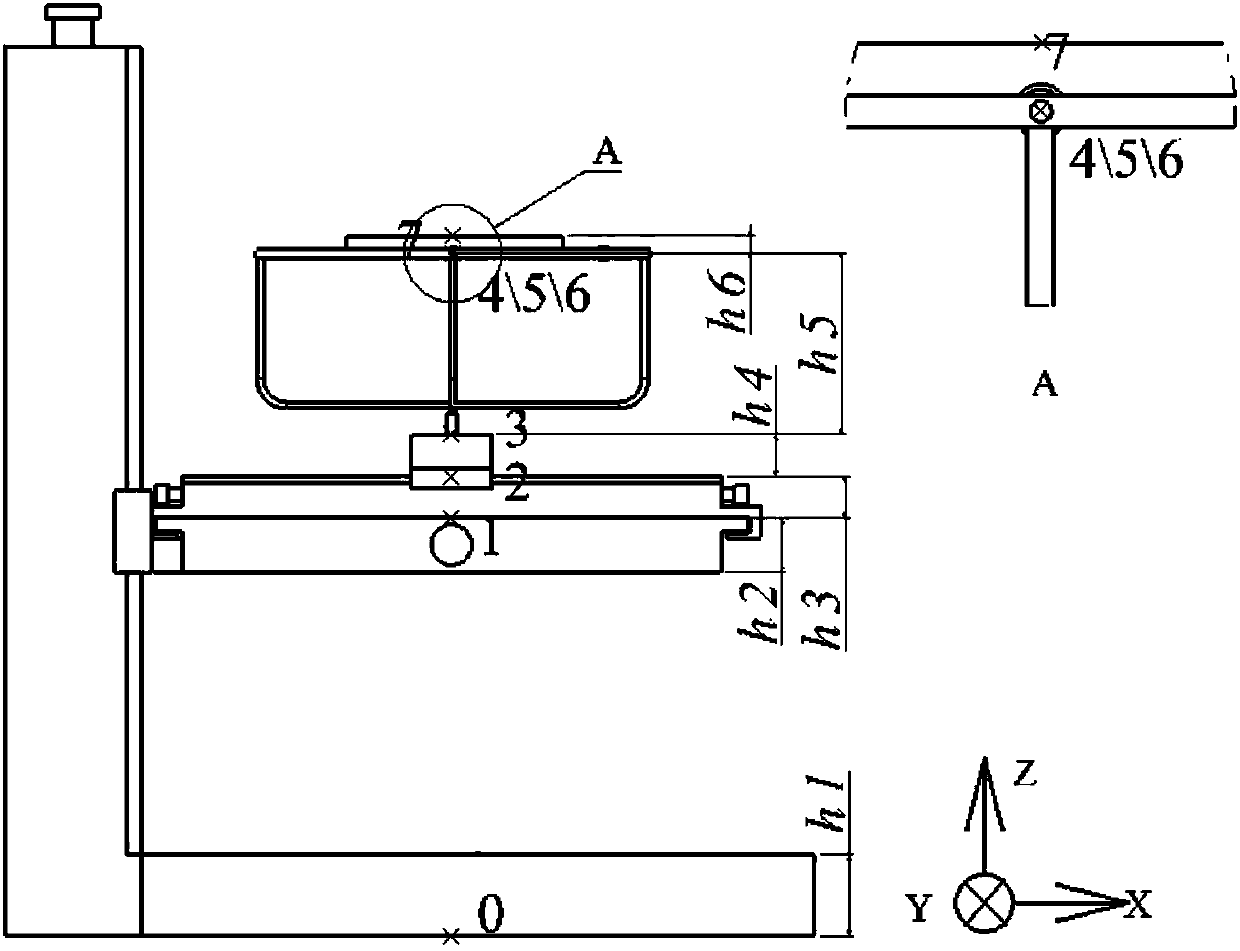
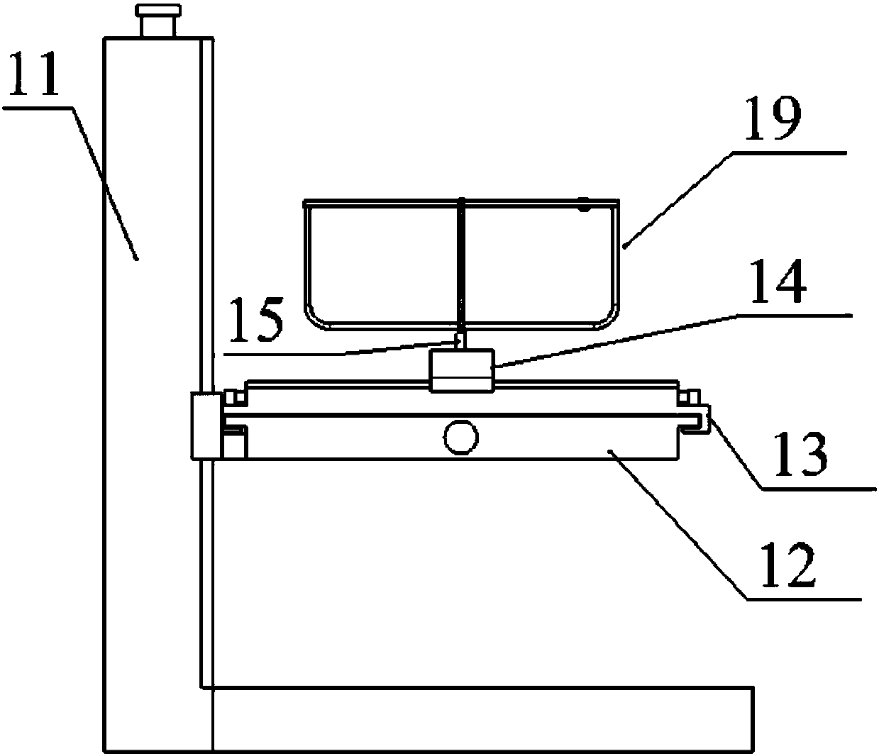
[0087] This embodiment provides a camera calibration system, including a calibration platform, the calibration platform includes an X-axis translation mechanism, a Y-axis translation mechanism, a Z-axis translation mechanism; an X-axis rotation mechanism, a Y-axis rotation mechanism, a Z-axis rotation mechanism and Fixed platform; of which:

[0088] The Z-axis translation mechanism is arranged at the bottom of the entire calibration platform, including the base and the Z-axis movement platform, the Z-axis ball screw and the rotary encoder of the Z-axis translation mechanism; the Z-axis ball screw realizes the Z-axis movement of the platform in the Z direction. The movement of the Z-axis translation mechanism is used to record the rotation times of the Z-axis ball screw through the rotary encoder of the Z-axis translation mechanism, thereby recording the position of the Z-axis moving platform in the Z direction;

[0089] The Y-axis translation mechanism includes a Y-axis mobile...

Embodiment 2

[0101] This embodiment provides a calibration method for a camera calibration system, including any one of the following processes:

[0102] - traditional calibration process;

[0103] - Self-calibration process.

[0104] specifically:

[0105] (1) Traditional calibration method

[0106] The specific steps of Zhang Zhengyou's calibration method using the calibration system provided in Example 1 are introduced here:

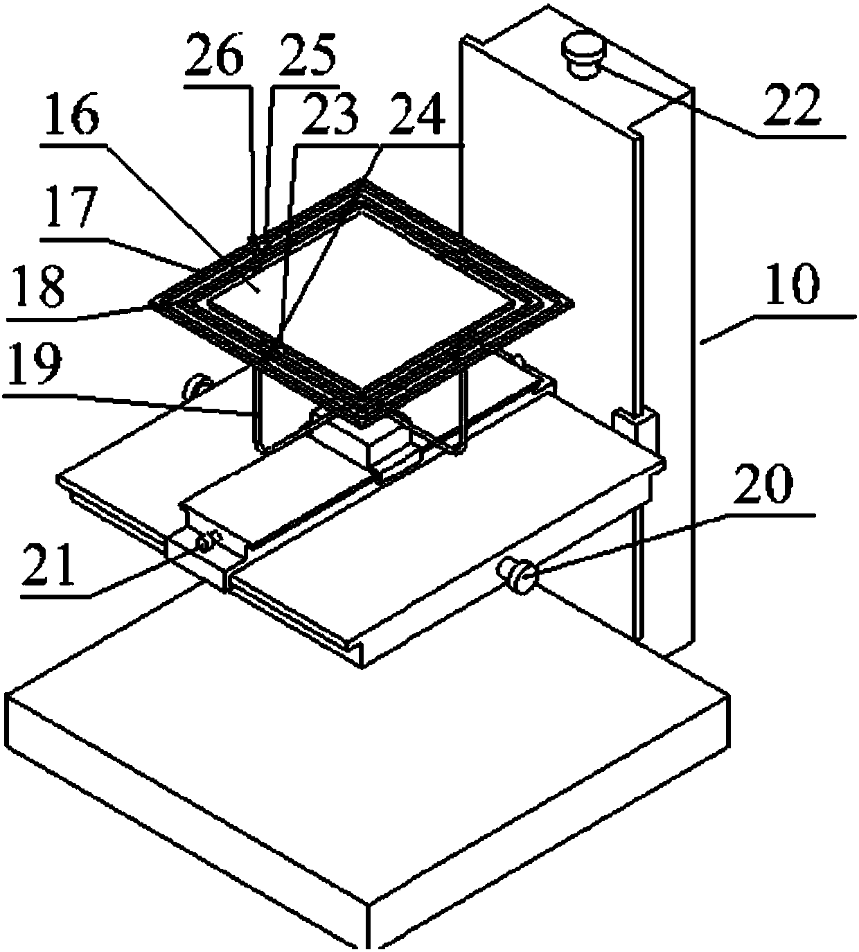
[0107] The first step: place the calibration platform 10 at a suitable horizontal position, fix the camera 28 at an appropriate position directly above the calibration platform 10; fix the calibration plate 27 on the fixed platform;

[0108] Second step: adjust the X-axis rotation knob 24 of the X-axis rotation bracket, the Y-axis rotation knob 26 of the Y-axis rotation bracket, and the Z-axis rotation knob of the Z-axis rotation bracket 19, so that the X-axis rotation mechanism rotates the encoder 23, Y The rotation angles of the axis rotation mechanism rotar...


PUM


Abstract

The invention provides a camera calibration system. A calibration platform of the camera calibration system comprises an X-axis translation mechanism, a Y-axis translation mechanism, a Z-axis translation mechanism, an X-axis rotation mechanism, a Y-axis rotation mechanism, a Z-axis rotation mechanism and a fixed platform, and has 6 degrees of freedom. Meanwhile, the invention provides a calibration method of the camera calibration system. The method comprises the following steps of: establishing a coordinate system of each axis according to size parameters of the calibration platform; and obtaining a position and a direction of a calibration plate or a reference substance at any moment through recording a position of each axis by an encoder of each axis, so as to further realize translation and rotation of the calibration plate or the reference substance in any direction. The camera calibration system is capable of replacing robot platform to calibrate internal and external parametersof cameras, customized clamps fixedly connected between robots and the tail ends of the cameras are not required, and the traditional calibration method and self-calibration method can be convenientlyused, so that the system is simple to operate and flexible to use; and compared with the working manner of moving the cameras by the robots, the manner of carrying out calibration through moving thecalibration plate or the reference substance has the effect of greatly reducing the mistaken operation probability.

Description

technical field [0001] The invention relates to the technical field of camera calibration, in particular to a camera calibration system and a calibration method thereof. Background technique [0002] The camera is used in the machine vision system to obtain the target image to realize the reconstruction and recognition of the object. The premise of realizing the above functions is to establish a geometric model between the three-dimensional information of a certain point on the space object and the two-dimensional coordinate information in the image, and the parameters of the geometric model are the internal and external parameters of the camera and the light plane equation of the camera. Internal and external parameters and optical parameters need to be calibrated through experiments and calculations, so the accuracy of parameter calibration directly affects the accuracy of machine vision. [0003] At present, a variety of methods have been proposed for camera calibration,...

Claims


Application Information

Patent Timeline
Patent Type & Authority Applications(China)
IPC IPC(8): G06T7/80
CPCG06T7/80
Inventor 张轲秦涛邓景煜
Owner SHANGHAI JIAO TONG UNIV
Why Eureka
Try Eureka