Integrated roof power generation system of building

A technology for power generation systems and buildings, applied in the field of building-integrated roof power generation systems, can solve problems such as high risk of water leakage and failure of drainage structures.

Pending Publication Date: 2018-03-16
HANGZHOU SONNY ENERGY TECH CO LTD
View PDF11 Cites 4 Cited by
  • Summary
  • Abstract
  • Description
  • Claims
  • Application Information

AI Technical Summary

Problems solved by technology

[0003] The traditional building-integrated roof power generation system uses screws to perforate the drainage structure, and the number of perforations is large, and the risk of water leakage is high. If it is not handled properly, the drainage structure will fail

Method used


Image

  • Integrated roof power generation system of building
  • Integrated roof power generation system of building
  • Integrated roof power generation system of building

Examples


Embodiment Construction

[0022] The present invention will be further described below in conjunction with the accompanying drawings.

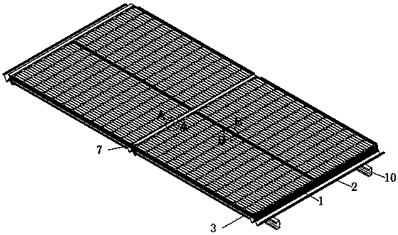
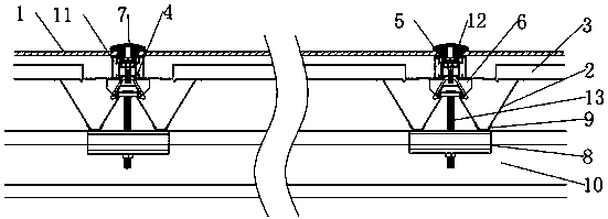
[0023] As shown in the figure, a building-integrated roof power generation system includes a main water tank 2 , a photovoltaic module 1 , a pressing block 5 and a spacer 6 , wherein the photovoltaic module 1 is composed of a photovoltaic panel and a module frame 11 .

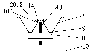
[0024] The cross section of the main water tank 2 is W-shaped, which specifically includes a main support part 201 arranged in the middle of the main water tank 2, auxiliary support parts 202 arranged on both sides of the main water tank 2 and arranged between the main support part 201 and each auxiliary support part 202 Concave drainage grooves 203 between them. The two side walls of the upper end of the main supporting part 201 protrude outward to form an undercut 2011 . As a preferred structure, undercuts 2011 are provided on both side walls of the main support part 201 along the length direction of...


PUM


Abstract

The invention relates to an integrated roof power generation system of a building. The system is composed of a main water tank, photovoltaic assemblies, pressing blocks and cushion blocks. The main water tank consists of a main supporting part, auxiliary supporting parts and drainage channels; the two side walls of the main supporting part protrude outwardly to form inverted buckles; chutes are formed at parts, corresponding to the inverted buckles, in the two side walls of the main supporting part; the inverted buckles are connected with photovoltaic assembly fixed elements in a buckling manner; the cushion blocks are arranged on the photovoltaic assembly fixed elements cooperatively; and the bottoms of the cushion blocks are in contact with the main supporting part and the photovoltaic assemblies are arranged at the two sides of the cushion blocks. The pressing blocks are pressed between the photovoltaic assemblies and are fixed with the photovoltaic assembly fixed elements by boltsto compress the photovoltaic assemblies. Water-proof covers are arranged on the pressing blocks; sliding blocks are arranged in the chutes; sliding block bolts are arranged in the sliding blocks and are connected with clamping blocks to fix the main water tank and C-shaped purlines. Therefore, a water leakage problem caused by penetration and fixation of the bolt in the prior art is solved; and the photovoltaic assemblies are installed conveniently.

Description

technical field [0001] The invention relates to a building integrated roof power generation system. Background technique [0002] Building integration is the integration of solar energy utilization into the overall design of the building, integrating architecture, technology and aesthetics. The building-integrated roof power generation system perfectly realizes the combination of solar photovoltaic power generation and buildings. In the building-integrated roof power generation system, how to achieve effective and stable connection, waterproof and drainage, and anti-leakage is the main research direction of the building-integrated roof power generation system. [0003] The traditional building-integrated roof power generation system uses screw perforations to fix the drainage structure, and the number of perforations is large, and the risk of water leakage is high. If it is not handled properly, the drainage structure will fail. Contents of the invention [0004] Aiming ...

Claims


Application Information

Patent Timeline
Patent Type & Authority Applications(China)
IPC IPC(8): H02S20/23H02S30/00F24S25/634
CPCH02S20/23H02S30/00Y02B10/20Y02E10/50Y02A30/60Y02B10/10
Inventor 李新富胡纯星陈峰
Owner HANGZHOU SONNY ENERGY TECH CO LTD
Why Eureka
Try Eureka