
Hardware part casting working table

A technology for hardware parts and workbenches, which is applied in the field of metal parts casting workbenches, can solve the problems of inconvenient movement, heavy casting workbenches, and inability to fix rollers on the ground, etc., and achieves the effects of convenient operation, avoiding shaking, and simple structure

Inactive Publication Date: 2018-03-20
柳州市钜嘉机械有限公司
View PDF9 Cites 7 Cited by
  • Summary
  • Abstract
  • Description
  • Claims
  • Application Information

AI Technical Summary

Problems solved by technology

[0003] At present, most of the casting process is to cast the commonly used hardware parts, and the casting of the hardware parts is mostly completed on the casting workbench. In the existing technology, the casting workbench of the hardware parts is relatively heavy, and it is very inconvenient to move. Most metal casting workbenches are equipped with rollers at the bottom to facilitate movement, but when the metal workbench moves to the casting position, the rollers cannot be fixed on the ground well, so the casting platform is easy to shake when casting , has brought trouble to the casting of hardware parts, so the present invention proposes a solution to the above problems

Method used


Image

  • Hardware part casting working table
  • Hardware part casting working table
  • Hardware part casting working table

Examples


Embodiment

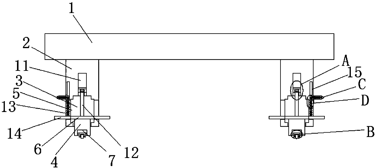
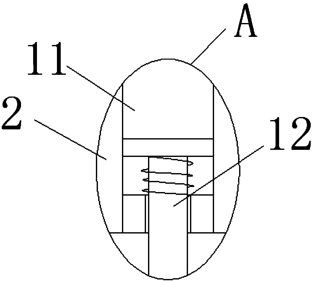
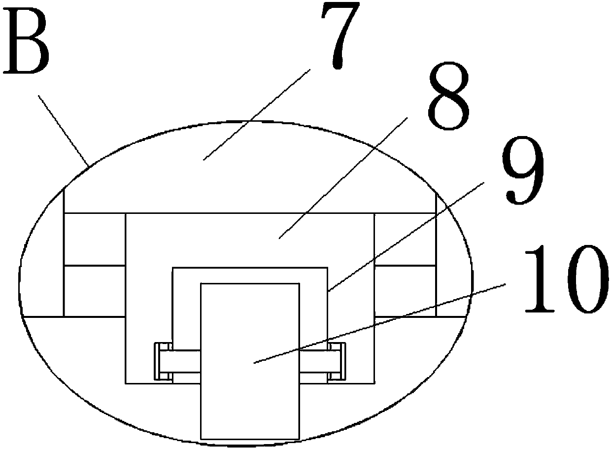
[0022] refer to Figure 1-5 , this embodiment proposes a casting workbench for hardware parts, including an operation platform 1, a plurality of support feet 2 are fixedly installed on the bottom of the operation platform 1, and a first installation groove 3 is opened on the bottom of the support feet 2, and the first installation groove A mounting block 4 is slidably installed inside the mounting block 3, and the bottom of the mounting block 4 extends to the outside of the first mounting groove 3. A telescopic assembly is arranged above the mounting block 4. The telescopic assembly includes symmetrical openings on the inner walls of the first mounting groove 3. The first limiting groove 5, the top of the mounting block 4 is fixedly installed with the first limiting block 6, and the two sides of the first limiting block 6 are respectively slidably installed in the corresponding first limiting groove 5, and the supporting feet 2 There are square through holes 13 symmetrically o...


PUM


Abstract

The invention discloses a hardware part casting working table comprising an operation platform. Multiple supporting legs are fixedly installed at the bottom of the operation platform. First installation grooves are formed in the bottoms of the supporting legs. Installation blocks are installed in the first installation grooves in a sliding manner. The bottoms of the installation blocks extend outof the first installation grooves. Telescopic assemblies are arranged above the installation blocks. Each telescopic assembly comprises first limiting grooves symmetrically formed in the inner walls of the two sides of the corresponding first installation groove. First limiting blocks are fixedly installed on the tops of the installation blocks. The two sides of each first limiting block are installed in the corresponding first limiting grooves in a sliding manner correspondingly. The hardware part casting working table is simple in structure and convenient to operate, rolling wheels can be very conveniently collected in the first installation grooves, the rolling wheels can be fixed in the first installation grooves after being collected, and the trouble caused by shaking of the operationplatform to casting of hardware parts is avoided.

Description

technical field [0001] The invention relates to the technical field of casting workbenches, in particular to a casting workbench for hardware parts. Background technique [0002] Casting is a relatively early metal thermal processing technology mastered by humans. It has a history of about 6,000 years. China has entered the heyday of bronze castings between 1700 BC and 1000 BC. The technology has reached a very high level. Casting is a method of casting liquid metal into a casting cavity that is suitable for the shape of the part. After it is cooled and solidified, the method of obtaining parts or blanks is mostly the metal that is originally solid but heated to liquid state. The material can be sand, metal or even ceramics, and the methods used will vary according to different requirements. [0003] At present, most of the casting process is to cast the commonly used hardware parts, and the casting of the hardware parts is mostly completed on the casting workbench. In the ...

Claims


Application Information

Patent Timeline
IPC IPC(8): B22C19/02
CPCB22C19/02
Inventor 王小华梁程鹏
Owner 柳州市钜嘉机械有限公司
Learn More