Machine tool spindle with annular jetting type cooling device

A cooling device, machine tool spindle technology, applied in metal processing machinery parts, large fixed members, maintenance and safety accessories, etc., can solve the problems of low utilization rate of coolant, limited cooling capacity, affecting processing accuracy, etc. Dimensional accuracy, low manufacturing cost and maintenance cost, improved cooling effect and the effect of

Pending Publication Date: 2018-03-20
黄石百斯特智能科技有限公司
View PDF0 Cites 7 Cited by
  • Summary
  • Abstract
  • Description
  • Claims
  • Application Information

AI Technical Summary

Problems solved by technology

During mechanical processing, a lot of heat will be generated between the tool and the processing parts. If the heat is not removed in time, the tool will wear faster, or even be damaged or broken, which will seriously affect the machining accuracy.
In the existing cooling device, an external cooling pipe is usually used to cool the tool, and its position during the machining process is fixed. The coolant flows from the top of the tool to the bottom of the tool. The flow rate of the coolant is slow, and the cooling The ability is limited, and the purpose of flushing iron filings cannot be achieved, and it cannot meet the requirements for the use of high-speed and high-precision CNC machine tools
At the same time, some machine tool spindles use built-in cooling pipes, but there is a phenomenon of coolant splashing, resulting in low utilization of coolant and difficult to clean the machine tool

Method used


Image

  • Machine tool spindle with annular jetting type cooling device
  • Machine tool spindle with annular jetting type cooling device
  • Machine tool spindle with annular jetting type cooling device

Examples


Embodiment Construction

[0020] The following will clearly and completely describe the technical solutions in the embodiments of the present invention with reference to the accompanying drawings in the embodiments of the present invention. Obviously, the described embodiments are only some, not all, embodiments of the present invention. Based on the embodiments of the present invention, all other embodiments obtained by persons of ordinary skill in the art without making creative efforts belong to the protection scope of the present invention.

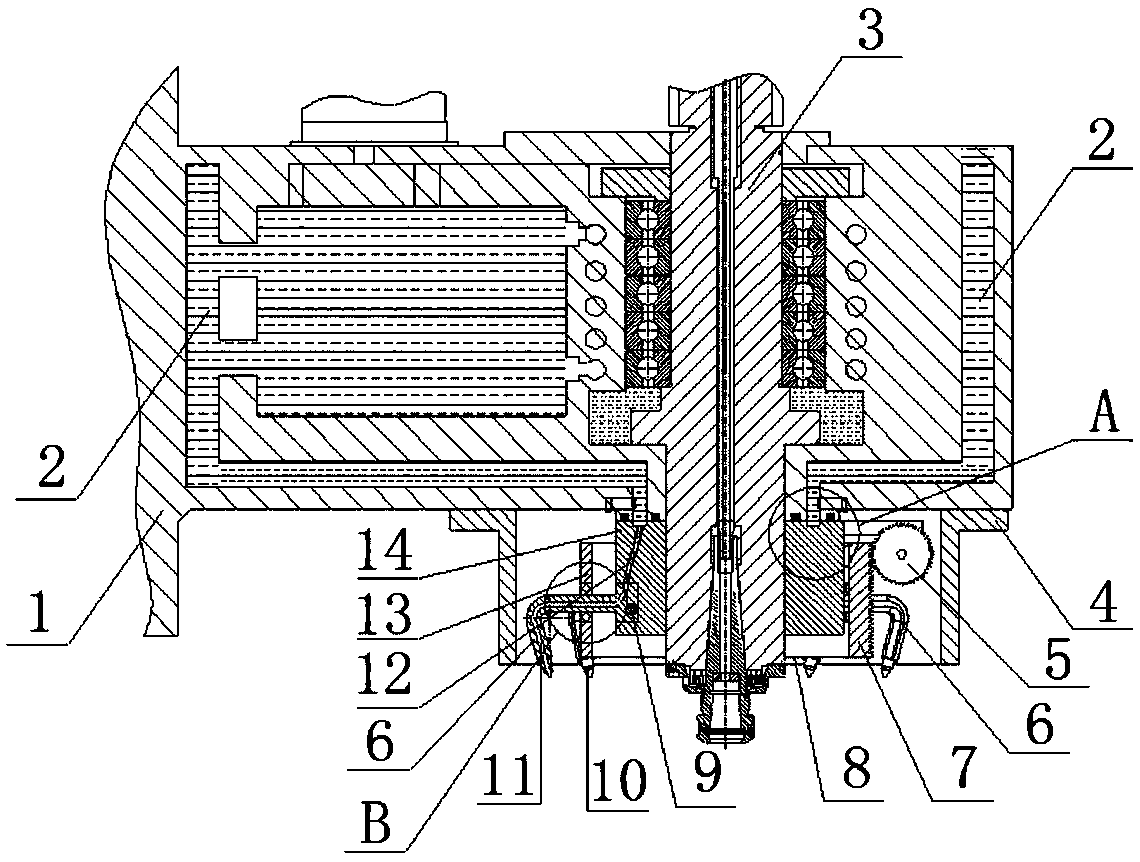
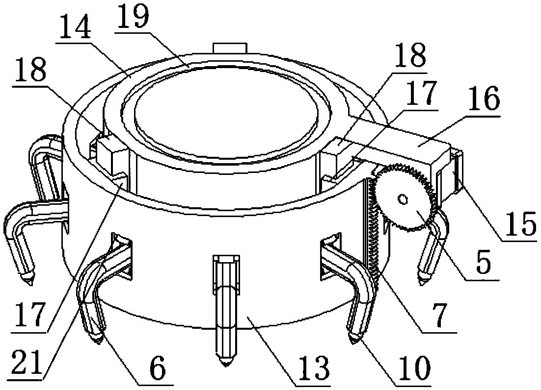
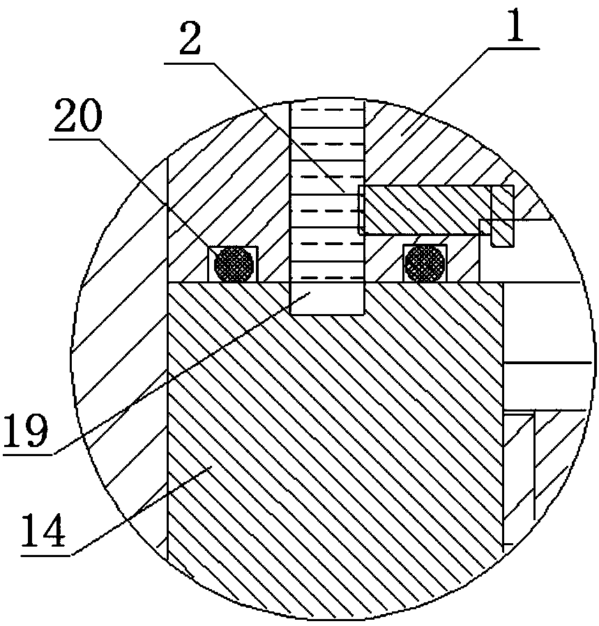
[0021] refer to Figure 1 to Figure 4 , a machine tool spindle with an annular jet cooling device, comprising a headstock body 1, a spindle 3 disposed inside the headstock body 1, and a high-pressure coolant 2 surrounding the inner wall of the headstock body 1, the The lower end of the spindle box body 1 is connected with an annular jet cooling device 8, and the annular jet cooling device 8 is set outside the lower end of the main shaft 3;

[0022] The annula...


PUM


Abstract

The invention discloses a machine tool spindle with an annular jetting type cooling device. The machine tool spindle comprises a spindle box body, a spindle arranged in the spindle box body and high-pressure cooling liquid arranged on the inner wall of the spindle box body in a surrounding mode, and the annular jetting type cooling device is connected to the lower end of the spindle box body. Theannular jetting type cooling device comprises a base, guide rails, sliding blocks, a circular-ring-shaped sliding sleeve, a rack, a gear, a motor, a motor installing plate, 7-shaped nozzle brackets and high-pressure nozzles, wherein an annular groove is formed in the upper end face of the base, a communicating hose is arranged in the base, a cooling liquid channel is arranged in each nozzle bracket, and the annular groove, the communicating hose, the cooling liquid channels and the high-pressure nozzles communicate with one another in sequence to form a cooling liquid pipeline. According to the machine tool spindle with the annular jetting type cooling device, the tool cooling effect and machining precision are improved, the structural principle is simple, the manufacture cost and the maintenance cost are low, and use is convenient and reliable.

Description

【Technical field】 [0001] The invention relates to the technical field of mechanical processing equipment, in particular to a machine tool spindle with an annular jet cooling device. 【Background technique】 [0002] In mechanical processing equipment, the main shaft is one of the most basic components of the machine tool. One end of the spindle is connected with a processing tool to process mechanical parts, and the other end is connected with a motor, which drives it to rotate or rise and fall. During mechanical processing, a lot of heat will be generated between the tool and the processing parts. If the heat is not removed in time, the tool will wear faster, or even be damaged or broken, which will seriously affect the machining accuracy. In the existing cooling device, an external cooling pipe is usually used to cool the tool, and its position during the machining process is fixed. The coolant flows from the top of the tool to the bottom of the tool. The flow rate of the co...

Claims


Application Information

Patent Timeline
Patent Type & Authority Applications(China)
IPC IPC(8): B23B19/02B23Q11/10B23Q11/00
CPCB23Q1/70B23Q11/00B23Q11/0042B23Q11/10
Inventor 方辉陈健
Owner 黄石百斯特智能科技有限公司
Why Eureka
Try Eureka