Antenna with heat dissipation function

An antenna and functional technology, applied in the field of antennas with heat dissipation function, can solve the problems of poor thermal performance and damage of antennas, and achieve the effect of reducing the probability of failure and superior cooling

Inactive Publication Date: 2019-11-15
武汉慧联无限科技有限公司
View PDF5 Cites 0 Cited by
  • Summary
  • Abstract
  • Description
  • Claims
  • Application Information

AI Technical Summary

Problems solved by technology

[0003] Due to the poor thermal performance of the existing antenna, it is easy to be damaged due to excessive heat, so it is necessary to increase the heat dissipation performance of the antenna branch

Method used


Image

  • Antenna with heat dissipation function
  • Antenna with heat dissipation function

Examples


Embodiment Construction

[0022] In order to solve the above existing technical problems, the present invention proposes the following solutions, which will be clearly and completely described below in conjunction with specific embodiments of the application and corresponding drawings. Apparently, the described embodiments are only some of the embodiments of the present application, rather than all the embodiments. Based on the embodiments in this application, all other embodiments obtained by persons of ordinary skill in the art without making creative efforts belong to the scope of protection of this application.

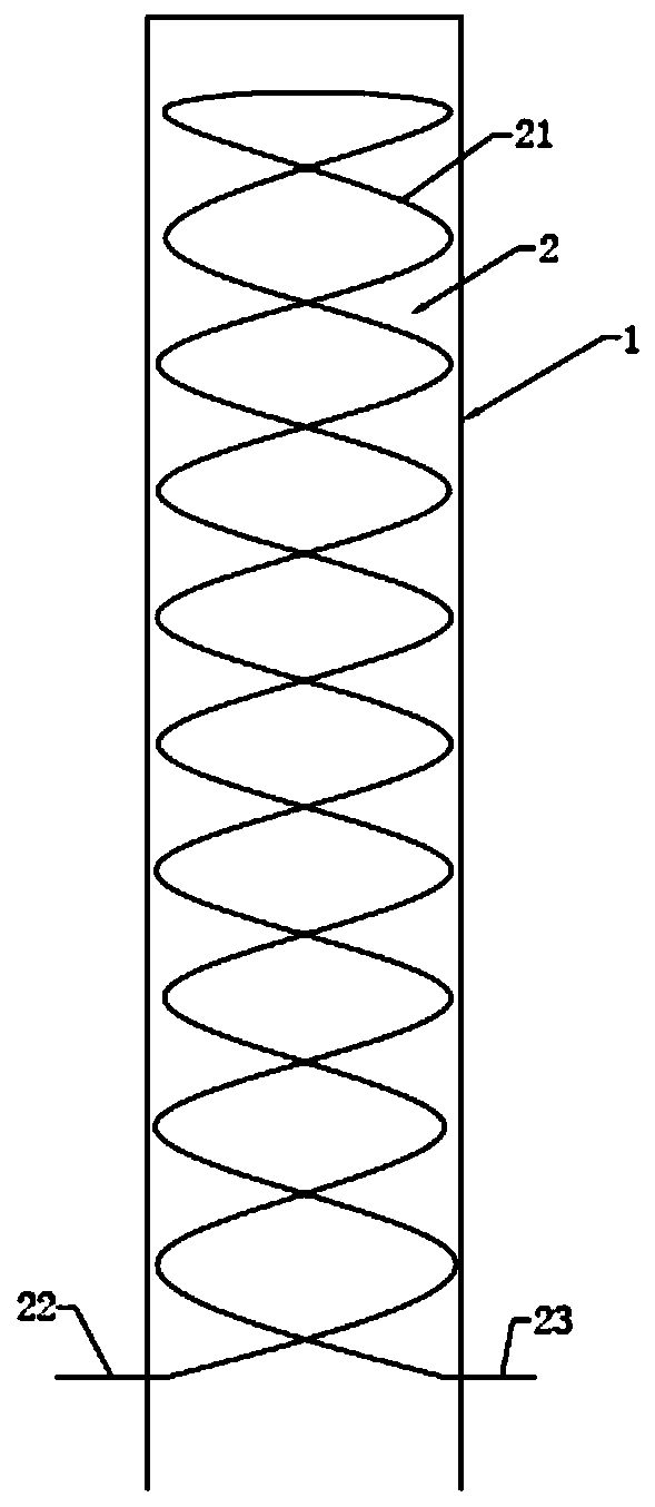
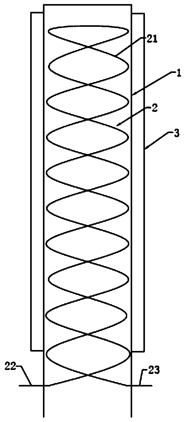
[0023] figure 1 A structural diagram of an antenna with a heat dissipation function provided for Embodiment 1 of this specification. The device includes an antenna branch 1 and a condensation device 2 that are hollow inside. The antenna branch 1 is the protruding part of the antenna. In order to receive signals better, the antenna The antenna stub 1 will be set longer.

[0024] The conde...


PUM


Abstract

The invention discloses an antenna with a heat dissipation function. The device includes an internally hollow antenna branch and a condensation device. The condensation device includes a water inlet for injecting cold water, a water outlet for discharging hot water and a water storage mechanism arranged inside the antenna branch. The water storage mechanism is a hollow cylindrical pipe with a helical side wall. The condensation device assists in the heat dissipation of the antenna branch, so that the antenna can work normally, and the probability of failure is reduced. Fresh cold water is injected from the water inlet of the condensation device and flows through the water storage mechanism inside the antenna branch to cool the inside of the antenna branch so as to facilitate the heat dissipation of the antenna, and finally, the hot water after cooling is discharged from the water outlet of the condensation device. Because cold water can be injected into the water storage mechanism of the condensation device in real time, the condensation device can cool the antenna branch in real time, and the antenna can work normally.

Description

technical field [0001] The present application relates to the technical field of wireless communication, and in particular to an antenna with a heat dissipation function. Background technique [0002] The radio frequency signal power output by the radio transmitter is sent to the antenna through the feeder (cable), and is radiated by the antenna in the form of electromagnetic waves. After the electromagnetic wave reaches the receiving location, it is followed by the antenna (receiving only a small part of the power), and sent to the radio receiver through the feeder. It can be seen that the antenna is an important radio device for transmitting and receiving electromagnetic waves, and there is no radio communication without the antenna. With the development of communication technology, wireless communication devices such as mobile phones, personal digital assistants, and notebook computers have been widely used. These wireless communication devices use antennas to receive an...

Claims


Application Information

Patent Timeline
IPC IPC(8): H01Q1/50H01Q1/00
CPCH01Q1/02H01Q1/50
Inventor 杨广学
Owner 武汉慧联无限科技有限公司
Why Eureka
Try Eureka