Gas meter counter magnetic steel wheel automatic feeding device

A technology of gas metering and automatic feeding, applied in metal processing, metal processing equipment, manufacturing tools, etc., can solve the problems of unguaranteed assembly quality and efficiency, long time-consuming magnetic steel wheels, and prone to wrong assembly and missing assembly. , to reduce the number of manual feeding, improve feeding efficiency, and ensure the effect of orderly feeding

Inactive Publication Date: 2018-03-20
CSIC PRIDENANJINGINTELLIGENT EQUIP SYST CO LTD
7 Cites 4 Cited by

AI-Extracted Technical Summary

Problems solved by technology

[0002] At present, the loading and assembly of the magnetic steel wheel of the gas meter counter mostly adopts the method of manual loading and assembly. The manual loading and installation of the magnetic steel wheel takes a long time, the efficiency is low, and it is very easy to have wrong installation, missing installation, etc. Due ...

Method used

Before the digital wheel shaft 007 enters the shaft-passing mechanism, the compression cylinder 3502 drives the compression block 3501 to go down, and the digital wheel is compressed to prevent the position of the digital wheel from moving. The stopper 3504 blocks the end of the number wheel to ensure that the position of the number wheel shaft 007 is more accurate when it is inserted into the number wheel.
When adopting counter 009 digital wheel automatic feeding device of the present invention to carry out digital wheel automatic feeding, three digital wheel feeding mechanisms are arranged on horizontal frame one 1051, three digital wheel feeding mechanisms are provided with The seven material channels are...

Abstract

The invention discloses a gas meter counter magnetic steel wheel automatic feeding device. The gas meter counter magnetic steel wheel automatic feeding device comprises a second rack, an indexing material disc mechanism, a dragging lifting mechanism and a second transferring mechanism; the indexing material disc mechanism is mounted on the second rack, and comprises a cam divider, an indexing discis arranged on the cam divider, multiple material cylinders used for containing magnetic steel wheels are evenly distributed on the peripheral side of the indexing disc, and groove openings are formed in the outer sides of the material cylinders; the dragging lifting mechanism is arranged on one side of one material cylinder and comprises a servo lifting electric cylinder and a lifting bracket connected with the lower part of the servo lifting electric cylinder, one end of a lifting bracket is provided with a push plate inserted in the groove openings, and the second transferring mechanism isarranged above the dragging lifting mechanism and is used for clamping and transferring the magnetic steel wheels in the material cylinders. Automatic feeding of the magnetic steel wheels can be achieved, and the magnetic steel wheels can be effectively separated.

Application Domain

Technology Topic

Image

  • Gas meter counter magnetic steel wheel automatic feeding device
  • Gas meter counter magnetic steel wheel automatic feeding device
  • Gas meter counter magnetic steel wheel automatic feeding device

Examples

  • Experimental program(1)

Example Embodiment

[0043] The technical scheme of the present invention will be further described in detail below in conjunction with the accompanying drawings:
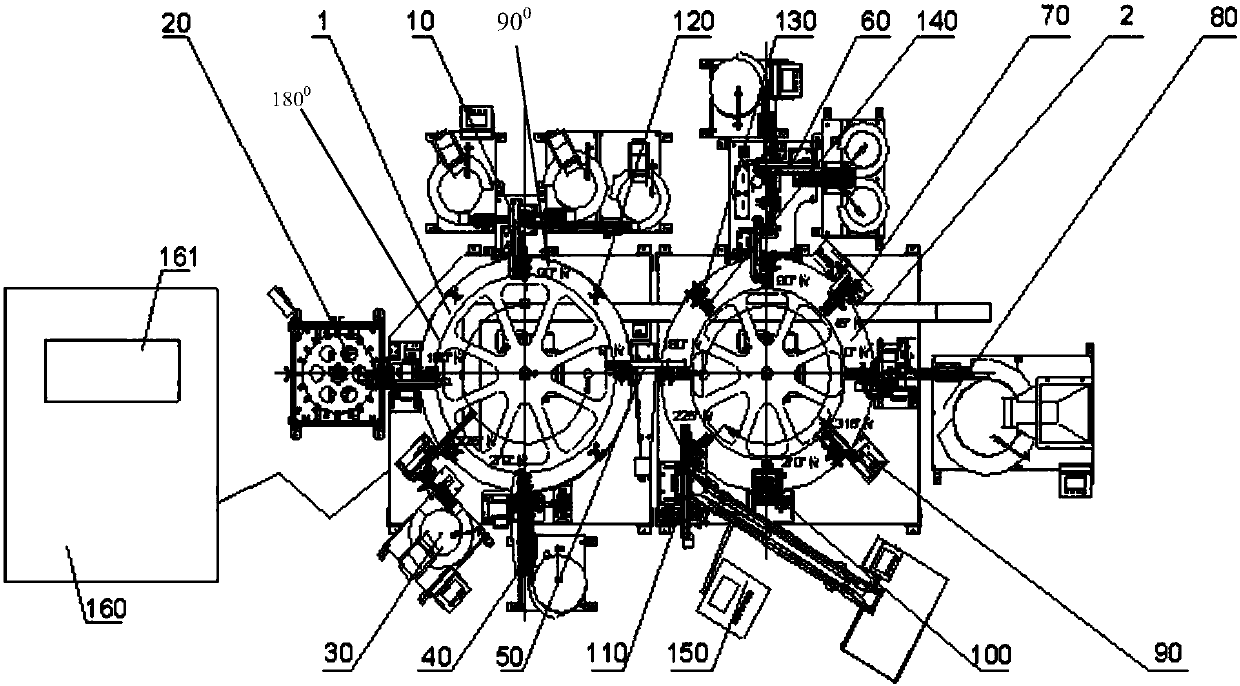
[0044] The invention is used to produce a mechanical digital counter for a gas meter, and its structure is as follows Figure 19 As shown, it is mainly composed of five black number wheels 004, two red character wheels 005, an initial character wheel 006, a number wheel axle 007, a switch axle 001, seven switch wheels 002 and a counter bracket 003. Each character wheel is evenly printed with the numbers 0, 1, 2, 3, 4, 5, 6, 7, 8, 9. After the assembly is completed, the number 0 on the eight character wheels of the qualified counter is on a straight line. When viewed from above, it coincides with the center line of the digital wheel axis. When the digital wheel assembly 010 and the switch wheel assembly 008 are correctly engaged, the switch wheel axis 001 is parallel to the digital wheel axis 007, and the counter bracket 003 is accurately engaged with the switch wheel axis 001 and the digital wheel axis 007.
[0045] The present invention is a magnetic steel wheel automatic feeding device in the automatic assembly equipment of a mechanical digital counter for a meter. The structure of the equipment is as follows figure 1 Shown:
[0046] a. There are two index plates arranged horizontally side by side with opposite rotation directions, including the character wheel index plate 1 and the assembly index plate 2;
[0047] b. The character wheel indexing plate 1 is provided with eight character wheel sorting transition tools 120 with an interval of 45 ゜;
[0048] c. Along the periphery of the character wheel indexing plate 1, there is a digital character wheel automatic feeding device 10, at the position of 90 ゜, an automatic magnetic steel wheel feeding device 20 is installed at the position of 180 ゜, and the first character wheel is installed at the position of 225 ゜. A digital wheel threading device 40 is installed at the material device 30 and 270゜;
[0049] d. The assembly index plate 2 is provided with eight sets of assembly tooling 130 and counter tooling 140 installed at the same angle with an interval of 45 ゜, the assembly tooling 130 is on the outside and the counter tooling 140 is on the inside;
[0050] e. Along the periphery of the assembly indexing plate 2, there is a counter bracket automatic feeding and pressing device 80 installed at the corresponding 0 ゜ position, a digital wheel dial device is installed at the 45 ゜ position, and a switch wheel set is installed at the 90 ゜ position. Shaft loading device 60, 225゜ position is equipped with counter offline device 110, 270゜ position is installed with visual inspection device 100, 315゜ position is installed with workpiece transfer device 90;
[0051] f. A digital wheel assembly transfer device 50 is installed between the position of the character wheel index plate 10 ゜ and the 180 ゜ position of the assembly index plate 2;
[0052] g. A control system 160 for controlling the index plates and devices described in a to f is provided, and the control system 160 has an Ethernet interface.
[0053] When the present invention works, the character wheel indexing plate 1 and the assembly indexing plate 2 rotate 45° each time, so that the character wheel sorting transition tool 120, the assembly tool 130, and the counter tool 140 are accurately docked and installed.
[0054] Wherein, the digital character wheel automatic feeding device 10 is used to automatically load and transfer the character wheel into the character wheel sorting transition tool 120;
[0055] The magnetic steel wheel automatic feeding device 20 is used to automatically load and transfer the character wheel with magnetic steel into the character wheel sorting transition tool 120;
[0056] The first character wheel feeding device 30 is used to automatically load and transfer the first character wheel into the character wheel sorting transition tool 120;
[0057] The digital wheel shaft threading device 40 is used to automatically thread the character wheel set to form a digital wheel assembly;
[0058] The character wheel sorting transition tool 120 is used for digital wheel group positioning;
[0059] The digital wheel assembly transfer device 50 is used to transfer the digital wheel assembly into the corresponding digital wheel assembly mold base 131 in the assembly tool 130;
[0060] The switch wheel set shaft threading and feeding device 60 is used to assemble and thread the switch wheel set to form a switch wheel assembly;
[0061] The digital wheel dial device 70 is used to dial the digital wheel group to the initial position;
[0062] The counter bracket automatic feeding and pressing device 80 is used to automatically load and press the counter bracket;
[0063] The workpiece transfer device 90 is used to transfer the assembled counter from the assembly tool 130 into the counter tool 140;
[0064] The visual inspection device 100 is used to detect the consistency of the numbers displayed by the counter digital wheel in the counter tool 140;
[0065] The counter offline device 110 is used to automatically offline the counter finished product;
[0066] The assembly tool 130 is used for positioning and correct engagement of the switch wheel assembly and the digital wheel assembly.
[0067] Digital wheel automatic feeding device, such as figure 2 As shown, it includes a feeding mechanism, a separating mechanism 104 and a digital wheel transfer mechanism 105.
[0068] Feeding mechanism, such as figure 2 with 3 As shown, it includes a three-pass black-character wheel feeding mechanism 101, a double-pass red-character wheel feeding mechanism 102, and a dual-pass black-character wheel feeding mechanism 103. The three-pass black-character wheel feeding mechanism 101 is provided with three direct-vibrating material passages 1 1010, and the double-pass red word wheel 005 is provided with two direct-vibrating material passages 2 1020, and the dual-pass black word wheel feeding mechanism is provided. 103 is provided with two direct-vibrating material channels 1030; the seven direct-vibrating material channels are arranged in parallel, and the material channel openings are arranged oppositely, so that the seven digital wheels coming out of the seven direct-vibrating material channels can be on the same straight line.
[0069] Separation mechanism 104, such as figure 2 , 3 As shown in and 4, it is set directly below the forehearth of the seven direct-vibration foreboards, and is used to separate the seven digital wheels from the direct-vibration foreboard. The structure mainly includes a jacking separation assembly 1042 and a jacking drive assembly 1041 connected thereunder. After the seven digital wheels are discharged from their respective feeding mechanisms, they enter the seven direct-vibration forehearths. The jacking drive assembly 1041 drives the jacking separation assembly 1042 to rise, thereby accurately positioning and supporting the seven digital wheels to achieve seven The separation of a number wheel and seven feed channels.
[0070] Transfer mechanism one 105, such as figure 2 , 5 As shown in and 6, it is set directly above the forehearth of the seven direct-vibration foreheads. Including a frame 1051, the upper end of the frame 1051 is provided with a horizontal transfer assembly 1052, a lifting assembly 1053 is installed on the horizontal transfer assembly 1052, and a positioning shaft assembly 1054 is connected to the lifting assembly 1053; a positioning shaft assembly 1054 includes a wear A guide support shaft 1061 is horizontally connected on the shaft cylinder 1064 and the shaft-through cylinder 1064. When in action, the lifting assembly 1053 drives the positioning shaft assembly 1054 down, so that the height of the guide support shaft 1061 and the center hole of the digital wheel is consistent; then the shaft passing cylinder 1064 drives the guide support shaft 1061 to penetrate the seven digital wheels; finally, the lifting assembly 1053 drives the positioning shaft assembly 1054 to move upward, and at the same time, the horizontal transfer assembly 1052 moves horizontally, thereby transferring the digital wheel to the other side. The positioning shaft assembly 1054 is also provided with a paddle 1062 cylinder and seven paddles 1062, which are used to arrange the distance between the number wheels according to the distance between the paddles 1062, and at the same time to position the number wheels.
[0071] Specific implementation instructions:
[0072] When the counter 009 digital wheel automatic feeding device of the present invention is used for digital wheel automatic feeding, three digital wheel feeding mechanisms are arranged on the horizontal frame 1051, and the seven feeding channels set by the three digital wheel feeding mechanisms It is arranged side by side, and the seven material channels are of the same height and seamless connection, which can realize the simultaneous discharging of seven digital wheels; the separation mechanism 104 designed by the digital wheel separation mechanism 104 can realize the overall separation of the seven digital wheels from the material channel, and Carry out precise positioning; at the same time, the transfer mechanism 105 uses its own paddle 1062 and digital wheel shaft assembly, so that the seven digital wheels are accurately positioned and arranged in the guide support shaft 1061 according to the set distance, avoiding traditional clamping jaws The resulting digital wheel is easy to fall, and the digital wheel pitch cannot be positioned.
[0073] It can be seen that the present invention not only realizes the simultaneous feeding and positioning of seven digital wheels, but also makes the seven digital wheels stable and reliable during the transfer process without falling, and realizes the mutual distance and assembly process requirements of the seven digital wheels. The separation distance is the same, which greatly reduces manual workload, improves production efficiency and ensures assembly quality.
[0074] The automatic feeding device 2020 for the magnetic steel wheel of the gas meter counter of the present invention, such as Figure 7 As shown, it includes a second frame 201, an indexing tray mechanism 202, a dragging and lifting mechanism 203, and a second transfer mechanism 204.
[0075] Indexing tray mechanism 202, such as Figure 7 , 8, 12a and 12b, installed on the second frame 201. It includes a cam divider 2021. The rotating shaft of the cam divider 2021 is provided with an upper index plate 2023 and a lower index plate 2022 up and down. A number of barrels 2024 are evenly distributed around the upper index plate 2023 and the lower index plate 2022. In the figure, a barrel 2024 is taken as an example. The barrel 2024 is used to place magnet wheels. The number of magnet wheels depends on the height of the barrel 2024. The outer side of the barrel 2024 is provided with notches along its length.
[0076] Drag material lifting mechanism 203, such as Figure 7 with 9 As shown, it is arranged on one side of the indexing tray mechanism 202. Including a mounting bracket 2031, a servo lifting electric cylinder 2032 and a lifting bracket 2033. The servo-lifting electric cylinder 2032 is arranged above the mounting bracket 2031, the lower end of the servo-lifting electric cylinder 2032 is connected with a lifting bracket 2033, and one end of the lifting bracket 2033 is provided with a push plate toward the barrel 2024. In the initial position, the lifting bracket 2033 is located at the lower end of the barrel 2024, and the push plate is located directly below the notch. When the servo lifting electric cylinder 2032 drives the lifting bracket 2033 to move upward, the push plate is inserted into the notch and the material The magnetic steel wheel in the cylinder 2024 pushes upwards. When a magnetic steel wheel on the top of the material cylinder 2024 is removed, the servo lift electric cylinder 2032 drives the lifting bracket 2033 to move up a magnetic steel wheel station, thereby aligning the material cylinder 2024. Fill in the top position.
[0077] Transfer mechanism two 204, such as Picture 10 with 11 As shown, it is arranged above the dragging lifting mechanism 203 and is used to remove the uppermost magnetic steel wheel of the barrel 2024. The structure mainly includes a rodless cylinder 802 transfer assembly 2042, a clamping assembly 2040 and a magnetic steel wheel positioning assembly 2041. Among them, one end of the rodless cylinder 802 transfer assembly 2042 is connected with a lifting cylinder 2043 and a magnetic steel wheel positioning assembly 2041. The clamping assembly 2040 is connected to the bottom of the lifting cylinder 2043. During operation, the magnetic steel wheel positioning assembly 2041 accurately positions the magnetic steel wheel, and then the lifting cylinder 2043 drives the clamping assembly 2040 down and clamps the magnetic steel wheel. The clamping assembly 2040 is clamped from the top of the barrel 2024 After holding a magnetic steel wheel, the lifting cylinder 2043 drives the clamping assembly 2040 and the magnetic steel wheel to rise. Then, the rodless cylinder 802 transfer assembly 2042 transfers the clamping assembly 2040 holding the magnetic steel wheel to the other end, and completes the reclaiming and transferring work of the magnetic steel wheel.
[0078] Magnetic steel wheel positioning assembly 2041, such as Picture 10 with 11 As shown, the second lifting cylinder 2401 is included. The second lifting cylinder 2401 is connected to a positioning member 2402. One side of the positioning member 2402 is provided with a positioning cylinder 2403 and a separating cylinder 2404, which are arranged up and down. During operation, the second lifting cylinder 2401 drives the positioning member 2402 to descend. The positioning member 2402 fixes and positions the magnet wheel to be clamped. At the same time, the positioning cylinder 2403 extends to hold and fix the magnet wheel to be clamped from the side, and then separate the cylinder. 2404 stretches out to block and separate the magnetic steel wheel to be clamped in the uppermost layer of the barrel 2024 from the magnetic steel wheel below, thereby completing the separation and positioning of the magnetic steel wheel.
[0079] Specific implementation instructions:
[0080] When in use, the cylinder 2024 must be filled with magnetic steel wheels and installed on the circumference of the upper index plate 2023 and the lower index plate 2022 in sequence.
[0081] Start the machine, the second lifting cylinder 2401 drives the positioning member 2402 to descend. The positioning member 2402 fixes and positions the magnet wheel to be clamped. At the same time, the positioning cylinder 2403 extends to hold and fix the magnet wheel to be clamped from the side, and then separate the cylinder. 2404 stretches out to block and separate the magnetic steel wheel to be clamped in the uppermost layer of the barrel 2024 from the magnetic steel wheel below, thereby completing the separation and positioning of the magnetic steel wheel. After that, the lifting cylinder 2043 drives the clamping assembly 2040 down and clamps the magnetic steel wheel. After the clamping assembly 2040 clamps a magnetic steel wheel from the top of the barrel 2024, the lifting cylinder 2043 drives the clamping assembly 2040 and The magnetic steel wheel rises. Then, the rodless cylinder 802 transfer assembly 2042 transfers the clamping assembly 2040 holding the magnetic steel wheel to the other end, and completes the reclaiming and transferring work of the magnetic steel wheel.
[0082] After the uppermost magnet wheel of the barrel 2024 is taken away, the position is empty. At this time, the servo lifting electric cylinder 2032 drives the lifting bracket 2033 upwards, and the push plate of the lifting bracket 2033 is inserted into the slot along the way, thereby moving the magnetic steel wheel in the barrel 2024 upwards by a position of the magnetic steel wheel. The top position of the barrel 2024 is filled. At the same time, the transfer assembly has placed the clamped magnetic steel wheel elsewhere, and returns to the initial position again, clamps the magnetic steel wheel in the barrel 2024, and circulates sequentially to complete the flow transfer work of the magnetic steel wheel.
[0083] Digital wheel automatic threading device, such as Figure 13a , 13b As shown in and 14, it includes a base 301, a discharging mechanism 302, a distributing mechanism 303, a shaft pushing mechanism 304, a shaft threading mechanism, and a shaft blocking mechanism 305.
[0084] The discharging mechanism 302 is a vibrating tray discharging mechanism 302, which is installed above the machine base 301 and includes a discharging tube. The discharging mechanism 302 is used to orderly derive the digital wheel axle 007 from the discharging tube.
[0085] Push shaft mechanism 304, such as Figure 13a , 13b As shown in and 16, it includes a push shaft 3403 sliding assembly 3402 installed on frame three 3401 and frame three 3401. The push shaft 3403 sliding assembly 3402 includes a cylinder three and a push shaft 3403. The end of the push shaft 3403 away from the cylinder three is provided with a push shaft. 3403 guide seat (with guide holes inside). The pushing shaft 3403 of the pushing shaft mechanism 304 and the discharging tube of the discharging mechanism 302 are arranged in parallel and in the same direction.
[0086] Material distribution mechanism 303, such as Figure 13a , 13b As shown in and 15, they are set at the output ends of the pushing shaft mechanism 304 and the discharging mechanism 302, that is, the outlet position of the discharging pipe. The distributing mechanism 303 includes a base 3301, a lower sliding table assembly is provided on the base 3301, and an upper sliding table assembly is provided on the sliding table assembly. The lower sliding table assembly includes a guide rail, on which a sliding table 3304 is slidably provided, and one end of the sliding table 3304 is provided with an air cylinder. The sliding direction of the sliding table 3304 is perpendicular to the axis of the discharge pipe. The upper sliding table assembly includes two guide rails fixed on a sliding table 1 3304, the guide rail two and the guide rail one are perpendicular, the guide rail two is provided with a sliding table 2 3302, one end of the sliding table 3302 is provided with a cylinder two, and the sliding table 2 3302 is provided There is a material distribution guide seat, the material distribution guide seat is opened with a material channel, the direction of the material channel is parallel to the discharge pipe, and when the piston rod of cylinder 1 in the figure is fully retracted into the cylinder, the material channel and the discharge pipe are the same Axis; when the piston rod of cylinder one is fully extended, the material channel and the push shaft 3403 are coaxial. On the side of the sliding table 1 3304 away from the pushing shaft mechanism 304 is provided a material distributing guide seat 3303 (with guide holes inside).
[0087] Threading mechanism, such as Figure 17 As shown, it is arranged on the side of the material distributing mechanism 303 away from the pushing shaft mechanism 304, and includes a counter pressing block 3501 and a pressing block cylinder 3502. A digital wheel assembly 010 is provided under the pressing block 3501. The digital wheel assembly 010 includes a The digital wheel, the digital wheel assembly 010 is transferred to the bottom of the compression block 3501 through other digital wheel feeding mechanisms; the counter compression block 3501 is driven by the compression block cylinder 3502 to compress the counter 009 digital wheel to prevent the counter 009 The position of the digital wheel moves during the shaft threading process;
[0088] Shaft blocking mechanism 305, such as Figure 17 As shown, it is arranged on the side of the shaft passing mechanism away from the pushing shaft 304, and includes a shaft block cylinder 3503 and a block 3504. The block shaft cylinder 3503 drives the block 3504 to move downward so that the block 3504 resists the pushing shaft 3403. Limit the end of the
[0089] Specific implementation instructions for the entire automatic assembly equipment of the mechanical digital counter of the meter:
[0090] First, put a number of digital axles 007 into the discharging mechanism 302, and the discharging mechanism 302 will sort out the digital axles 007 in an orderly manner. At the same time, the cylinder of the distributing mechanism 303 retracts and drives the sliding table 1 3304 to move to the side of the discharge pipe, so that the material channel of the distributing guide seat on the sliding table 2 3302 is aligned with the discharge pipe, and then the cylinder 2 drives the sliding table 2 3302 moves toward the discharge pipe, so that the material channel and the material pipe are connected, so that the digital wheel axle 007 from the material pipe will enter the material channel. When a digital wheel axle 007 enters the material channel, the discharge mechanism 302 stops discharging. . Then, the cylinder one pushes the sliding table 1 3304 out, so that the forehearth and the distribution guide seat 3303 are aligned; then, the cylinder two drives the sliding table 2 3302 to move, so that the forehearth and the distribution guide seat 3303 are connected.
[0091] After the docking is completed, the cylinder three-drive push shaft 3403 of the push shaft mechanism 304 pushes the digital wheel shaft 007 out of the material distributing guide seat 3303, and then enters the shaft threading mechanism.
[0092] Before the digital wheel axle 007 enters the shaft-through mechanism, the pressing cylinder 3502 drives the pressing block 3501 down to compress the digital wheel to prevent the position of the digital wheel from moving. At the same time, the shaft blocking cylinder 3503 of the shaft blocking mechanism 305 drives the block 3504 Block the end of the digital wheel to ensure that the position of the digital wheel axle 007 when it penetrates the digital wheel is more accurate.
[0093] Further as figure 1 As shown, when the present invention is working, the first character wheel feeding device 30 automatically feeds the first character wheel and accurately places it at the corresponding position in the character wheel sorting transition tool 120;
[0094] Further as figure 1 As shown, when the present invention is working, the digital wheel shaft device 40 automatically passes the digital wheel shaft 007 through all the center holes of the digital wheel in the character wheel sorting transition tool 120 and positions them to form a digital wheel assembly 010;
[0095] Further as figure 1 As shown in and 20, when the present invention is working, the digital wheel assembly transfer device 50 transfers the digital wheel assembly from the character wheel sorting transition tool 120 of the character wheel index plate 10 ゜ position to the assembly of the assembly index plate 180 ゜ position On the digital wheel assembly mold base 131 in the tooling 130;
[0096] Such as Figure 18 with 21 As shown, the switch wheel group automatic feeding and shaft threading device 60 mainly includes a vibrating tray 4 601, a vibrating tray 5 603, a vibrating tray 6 605 and a shaft distributing mechanism 602, a transfer manipulator 604 and a positioning tool 180 ゜ rotating plate 606, transfer manipulator two 607, push shaft mechanism 608. When the present invention works, it automatically feeds seven switch wheels through the switch wheel vibrating tray 5603 and vibrating tray 6605, and the transfer manipulator 604 grabs the switch wheel and places it on the 180゜ rotating disk 606 tooling with positioning tooling. Inside, forming a switch wheel group. The switch wheel shaft is loaded by the vibrating tray 601 and sent to the shaft distributing mechanism 602 to be divided into single branches, and then the switch wheel shaft and switch wheel group divided into single branches are perforated and assembled in the 606 tooling by the push shaft mechanism 608 to form the switch wheel assembly After 606 rotates 180°, the transfer manipulator 607 grabs the switch wheel assembly and transfers it to the switch wheel assembly mold base 132 in the assembly tool 130 on the assembly index plate 2;
[0097] Further as figure 1 with 21 As shown, when the present invention is working, the digital wheel setting device 70 makes the digital wheel set on the digital wheel assembly mold base 131 in the assembly tool 130 rotate around the digital wheel axis and reach the same angle through the limit block 134, and the digital wheel axis passes the limit Column 135 is limited, and the digital wheel number is dialed to the designated digital position. Simultaneously push the sliding mechanism 133 on the assembly tool 130 to correctly engage the digital wheel assembly with the switch wheel assembly;
[0098] Such as figure 1 , 19 As shown in and 20, the counter bracket automatic feeding and pressing device 80 is mainly composed of a vibrating material plate 800, a grasping mechanism 801, a rodless cylinder 802, a wheel positioning component 803, a displacement sensor 804, a material receiving mechanism 805, and an intermediate detection tool 806 composition. When the present invention works, it automatically feeds the counter bracket 003 to the material receiving mechanism 805 through the vibrating material tray 7800, and the grasping mechanism 801 grasps the counter bracket 003 from the material receiving mechanism 805 and transfers it to the material receiving mechanism 805 through the rodless cylinder 802. The middle detection tool 806, and then the displacement sensor 804 detects the distance between the middle point of the slot of the digital axle 007 in the counter bracket 003 and the middle point of the slot of the switch axle 001, and then further adjust the position so that the digital axle 007 and the switch axle 001 correspond to each other In the assembly notch on the counter bracket 003, move it to the top of the digital wheel assembly 010 and the switch wheel assembly 008 that are correctly engaged in the assembly tool 130, and then the wheel axis positioning component 803 will assemble the digital wheel axis 007 and the switch wheel axis in the assembly tool 130 001 is centered and positioned to ensure that the counter bracket 003 is accurate when pressed, and finally the gripping mechanism 801 with the counter bracket 003 is pressed down so that the engaged digital wheel assembly 010 and the switch wheel assembly 008 are installed into the counter bracket 003 to form a counter 009;
[0099] Further as figure 1 with 20 As shown, when the present invention is working, the workpiece transfer device 90 transfers the counter 009 from the assembly tool 130 to the counter tool 140;
[0100] Further as figure 1 with 20 As shown, when the present invention works, the visual inspection device 100 detects whether the number displayed by the counter 009 in the counter tool 140 at the specified position meets the set requirements, and the control system 160 automatically judges whether it is qualified or not according to the built-in standard;
[0101] Further as figure 1 with 20 As shown, when the present invention is working, the counter offline device 110 removes the counter 009 from the counter tool 140 while pushing the sliding mechanism 133 on the assembly tool 130 to reset;
[0102] Further as figure 1 As shown, when the present invention is working, the code spraying device 150 sprays codes on the outer surface of the bracket for the qualified counters, while the unqualified counters do not spray codes on the outer surface of the bracket.
[0103] Specific implementation instructions:
[0104] Step 1, the character wheel is automatically loaded: first, the non-magnetic steel digital wheel is automatically loaded, and the five black number wheels 004 and the two red character wheels 005 are automatically fed and transferred to the corresponding position of the character wheel sorting transition tool 120 . If the red character wheel 005 is equipped with magnetic steel, the next station 20 magnetic steel wheel automatic feeding device will complete the feeding and be transferred to the corresponding position of the character wheel sorting transition tool 120. The red character wheel 005 is with or without magnet. The steel is set by the human-computer interaction device 161 on the control system 160 according to the type of the counter to be produced, and the control system 160 automatically determines whether it is loaded with the black digital wheel 004 at the initial station or from the next station by the magnetic The steel wheel automatic feeding device 20 automatically feeds materials. Then the first character wheel 006 is automatically loaded and transferred to the corresponding position of the character wheel sorting transition tool 120 to form a digital wheel group;
[0105] Step two, the digital wheel set automatically threaded: the digital wheel shaft 007 automatically feeds and passes through the number wheel, the red character wheel and the middle hole of the initial wheel through the digital wheel threading device 40, and forms a through hole on the right side of the initial wheel. Digital wheel assembly of good shaft;
[0106] Step three, transfer the number wheel assembly: the number wheel assembly is automatically transferred from the character wheel sorting transition tool 120 set on the character wheel index plate 1 by the number wheel assembly transfer device 50 and placed on the assembly index plate 2 On the corresponding digital wheel assembly mold base 131 in the assembly tool 130;
[0107] Step four, the switch wheel group automatically feeds the shaft: the switch wheel shaft 001 and the switch wheel 002 are automatically fed by the switch wheel group automatic threading and feeding device 60 and the switch wheel shaft 001 passes through the middle hole of the switch wheel 002 to form the switch wheel assembly. Automatic transfer and place on the corresponding switch wheel assembly mold base 132 in the assembly tool 130;
[0108] Step 5, digital wheel set dialing: on the assembly index plate 2 through the digital wheel dialing device 70, each digital wheel of the digital wheel set rotates around the digital axle and reaches the same angle through the limit block, and the digital axle passes the limit Column limit, while pushing the sliding mechanism 133 on the assembly tool 130 to make the digital wheel assembly and the switch wheel assembly correctly mesh;
[0109] Step 6: Counter bracket 003 loading and pressing: The counter bracket 003 is automatically fed and pressed into the engaged digital wheel assembly and switch wheel assembly through the counter bracket automatic feeding and pressing device 80, and the digital wheel shaft and the switch wheel shaft pass through the counter bracket 003 Positioning and fixing of the inner card slot;
[0110] Step 7: Transfer the counter finished product: transfer the counter into the counter tool 140 set inside the assembly index plate 2 through the workpiece transfer device 90;
[0111] Step 8. Visual inspection: visual inspection is performed on the digital consistency displayed by the counter digital wheel in the counter tooling 140 after assembly, through the visual inspection device 100, and the control system 160 automatically judges whether it is qualified or not according to the built-in standard;
[0112] Step 9: Finished product off-line and coding: the counter finished product is automatically off-line through the counter off-line device 110, and the sliding mechanism 133 on the assembly tool 130 is reset at the same time, and then the coding device 150 performs the printing on the outer surface of the qualified counter Coding, the unqualified counter will not print the code on the outer surface of the bracket.
[0113] Those skilled in the art can understand that, unless otherwise defined, all terms (including technical and scientific terms) used herein have the same meanings as those commonly understood by those of ordinary skill in the art to which the present invention belongs. It should also be understood that terms such as those defined in general dictionaries should be understood as having meanings consistent with the meanings in the context of the prior art, and unless defined as here, they will not be used in ideal or overly formal meanings. Explanation.
[0114] The above embodiments are only to illustrate the technical ideas of the present invention, and cannot be used to limit the scope of protection of the present invention. Any changes made on the basis of the technical solutions based on the technical ideas proposed by the present invention fall into the protection scope of the present invention. Inside. The embodiments of the present invention are described in detail above, but the present invention is not limited to the above-mentioned embodiments, and various changes can be made without departing from the purpose of the present invention within the scope of knowledge possessed by those of ordinary skill in the art.

PUM

no PUM

Description & Claims & Application Information

We can also present the details of the Description, Claims and Application information to help users get a comprehensive understanding of the technical details of the patent, such as background art, summary of invention, brief description of drawings, description of embodiments, and other original content. On the other hand, users can also determine the specific scope of protection of the technology through the list of claims; as well as understand the changes in the life cycle of the technology with the presentation of the patent timeline. Login to view more.

Similar technology patents

Limiting mechanism for double-hole bushing

PendingCN110695882AReduce limit judgment timeSave the beatWork holdersMetal working apparatusControl theoryBushing
Owner:DALIAN ZHIYUN AUTOMATION

Automatic feeding and discharging single-truss mechanical hand of slicing machine

PendingCN113146596AShorten the horizontal length of the Y axisSave the beatProgramme-controlled manipulatorConveyor partsElectric machineryMotor shaft
Owner:连智(大连)智能科技有限公司

Classification and recommendation of technical efficacy words

  • Improve feeding efficiency
  • Save the beat

Feeding device for medical accessories

InactiveCN105173627ASpace-saving layoutImprove feeding efficiencyConveyor partsMedical instruments
Owner:MAIDER MEDICAL IND EQUIP

Three-rail vibrating plate

Owner:ACME ELECTRONICS KUNSHAN

Limiting mechanism for double-hole bushing

PendingCN110695882AReduce limit judgment timeSave the beatWork holdersMetal working apparatusControl theoryBushing
Owner:DALIAN ZHIYUN AUTOMATION

Automatic feeding and discharging single-truss mechanical hand of slicing machine

PendingCN113146596AShorten the horizontal length of the Y axisSave the beatProgramme-controlled manipulatorConveyor partsElectric machineryMotor shaft
Owner:连智(大连)智能科技有限公司
Why Eureka
Try Eureka