Battery cell feeding and discharging clamping jaw mechanism and battery cell assembly production line
A technology of battery clamps and jaws, which is applied in the direction of chucks, manipulators, conveyor objects, etc., can solve the problem of low tolerance, achieve high tolerance, avoid damage or safety hazards, and shorten the time for secondary positioning Effect
- Summary
- Abstract
- Description
- Claims
- Application Information
AI Technical Summary
Problems solved by technology
Method used
Image
Examples
no. 1 example
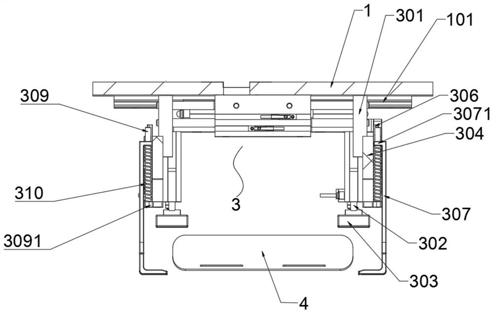
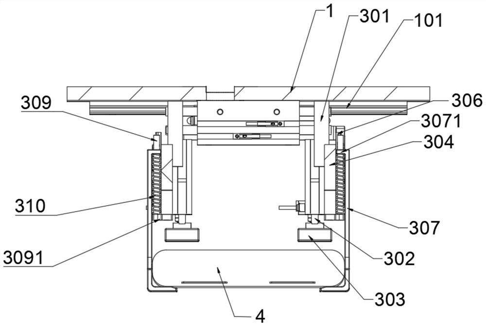
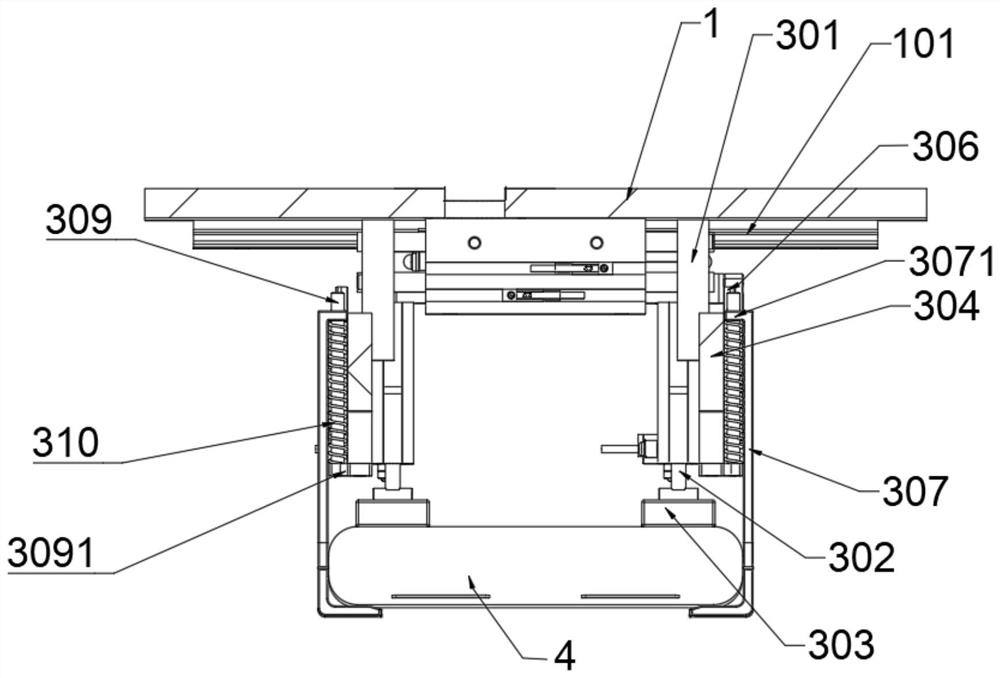
[0057] Such as figure 1 , figure 2 , image 3 , Figure 4As shown in other views, the cell loading and unloading jaw mechanism a includes: a mounting plate 1, the mounting plate 1 is connected to the Z-axis servo drive module 2 of the cell assembly production line through the Z-axis module connector 201, and the mounting plate 1 A mounting plate guide rail 101 is arranged below. Each mounting plate guide rail 101 is slidably connected to the gripper mechanism 3. The specific gripper mechanism 3 includes two gripper sliders 301, and the lower ends of the two gripper sliders 301 are respectively connected to the electric core push-down drive cylinder 302 through the connecting piece. , the cell is pressed down to drive the cylinder 302 to connect the cell to compress the POM board 303 longitudinally. The outer sides of the two jaw sliders 301 are connected to the longitudinal jaw slider guide rail 304, and a connecting slider 306 is arranged on the jaw slider guide rail 304...
no. 2 example
[0064] Please refer to the Figure 5 As shown in other views, based on the cell loading and unloading gripper mechanism a provided in the first embodiment of the present application, the second embodiment of the present application proposes another cell loading and unloading gripper mechanism a. The second embodiment is only a preferred mode of the first embodiment, and the implementation of the second embodiment will not affect the independent implementation of the first embodiment.
[0065] Specifically, the difference between the cell loading and unloading jaw mechanism a provided in the second embodiment of the present application is that each mounting plate 1 is set as two parallel mounting plate guide rails 101, and each mounting plate guide rail 101 Two sets of jaw mechanisms 3 as mentioned above are all set on the top. Two sets of gripper mechanisms 3 are arranged in parallel, and the distance control can be set to be adjustable by drive, or it can be set to meet the ...
no. 3 example
[0068] Please refer to the Figure 6 , Figure 7 As shown in other views, based on the cell loading and unloading gripper mechanism a provided in the second embodiment of the present application, the third embodiment of the present application proposes another cell loading and unloading gripper mechanism a. The third embodiment is only a preferred mode of the second embodiment, and the implementation of the third embodiment will not affect the independent implementation of the second embodiment.
[0069] The difference of the cell loading and unloading jaw mechanism a provided in the third embodiment of the present application is that the upper part of the mounting plate 1 is connected with the jaw rotating mechanism 5 .
[0070] Specifically, the claw rotation mechanism 5 includes a claw rotation mechanism mounting plate 501, which is integrally loaded and connected to other rotation mechanism components. The middle part of the claw rotation mechanism mounting plate 501 is p...
PUM
 Abstract
Description
Claims
Application Information
 - R&D
- Intellectual Property
- Life Sciences
- Materials
- Tech Scout
- Unparalleled Data Quality
- Higher Quality Content
- 60% Fewer Hallucinations
Browse by: Latest US Patents, China's latest patents, Technical Efficacy Thesaurus, Application Domain, Technology Topic, Popular Technical Reports.
© 2025 PatSnap. All rights reserved.Legal|Privacy policy|Modern Slavery Act Transparency Statement|Sitemap|About US| Contact US: help@patsnap.com


